
Anechoic chamber ( BEC ) - a room in which an echo does not occur. Anechoic chambers are of the following types:
- acoustic - in them there is no reflection of sound from the walls
- radio frequency - there is no reflection of radio waves from the walls
Typically, such cameras are designed so that they also isolate the camera from external signals (acoustic or radio frequency). All this allows you to measure the signal that came directly from the source, eliminating reflections from the walls and noise from the outside, thus forming the location of the source in free space.
The walls, ceiling and floor of such chambers are covered with material that absorbs the corresponding waves.
Content
- 1 Acoustic Anechoic Chambers
- 1.1 Sound absorbers
- 2 RF anechoic chambers
- 2.1 Coatings for the absorption of radio waves (Radar Absorbing Coating (RPP))
- 2.2 the dependence of the effectiveness of the frequency
- 2.3 Screened room
- 2.4 Camera size and handling
- 2.5 Use
- 2.6 Safety
- 3 Examples of parameters
- 4 References
- 5 notes
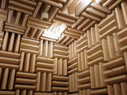
Anechoic Acoustic Chambers
Anechoic chambers are usually used in acoustics to simulate an unlimited space in which sound waves that have left the source never come back. In such chambers, measurement (construction) of radiation patterns (or sensitivity) of loudspeakers (or microphones ) is carried out; study the distribution of noise from industrial products [1] .
Sometimes in such cameras record or listen to music .
Sound Absorbers
Porous and fibrous materials are used ( polystyrene , polystyrene , felt , etc.).
In the USSR, music lovers sometimes built such chambers, pasting the walls of the room with embossed pallets (egg packaging) made of thick loose cardboard .
RF Anechoic Chambers
The interior of the RF camera is similar to an acoustic camera, however, instead of sound absorbers, a radio-absorbing material (RPM) is used to cover the surfaces.
Radiofrequency cameras are used to build radiation patterns of antennas , study electromagnetic compatibility and build EPR diagrams [2] . Measurements can be taken on full-sized objects, including airplanes , or on reduced models (with a corresponding reduction in the radar wavelength).
Radio frequency anechoic chambers using pyramidal absorbers of radio waves made of porous material partially have the properties of acoustic anechoic chambers.
Coatings for absorbing radio waves ( Radar Absorbing Coating (RPP))
These coatings are made from RPM and should absorb as many radio waves as possible coming from all possible directions. Otherwise, for example, when measuring electromagnetic compatibility and constructing antenna patterns, false (reflected) signals will arise, ambiguities in their interpretation and, ultimately, errors.
One of the most effective types of coating for chambers is gratings made of pyramid-shaped pieces of the absorber. Cells in the grill can be temporarily removed to accommodate equipment.
To be an effective absorber, an RPM must be neither a good conductor nor a good electrical insulator. The material should be something intermediate so that the radio waves penetrate into its thickness and decay there. A typical pyramid-absorber consists of a foamed rubber-like material containing a precisely selected mixture of graphite and iron powders (in the jargon of radio engineers is a “swamp”).
Another type of RPP is flat ferrite tiles covering all the internal surfaces of the chamber. This absorber takes up less space than pyramidal absorbers and can be laid on well-conductive surfaces. However, it is more expensive, but more durable than the pyramids, but less effective at high frequencies, due to the interaction only with the magnetic component of the EMP. It is used in cameras operating at frequencies below 1 GHz.
Frequency Efficiency
The efficiency of the camera is determined by the minimum radiation frequency at which the reflection from the walls begins to significantly exceed the reflection of high-frequency waves. Pyramidal absorbers are most effective when radiation with a wavelength is incident normally to the plane of their bases , and the height of the pyramids is approximately equal . Accordingly, increasing the heights of the pyramids increases the efficiency of the camera, but increases its cost and reduces the internal working volume.
Screened room
Radio-frequency anechoic chambers are usually placed in rooms isolated from external influences according to the Faraday cage scheme. The same screen prevents radio waves from leaking out of the camera.
Camera size and
In actual tests, an additional room is usually required to house the measuring equipment.
The size of the camera itself depends on the type of measurement required. For example, the criterion for the difference between the near and far fields of the emitter sets the minimum distance between the antennas of the transmitter and receiver. In accordance with this, and taking into account that space is required to accommodate radiation absorbers, the estimated size of the camera can be very large. For most firms, the cost of creating a large anechoic chamber is too high, unless this camera is used continuously. (We have to resort to tests on smaller models).
Anechoic chambers must comply with relevant standards and must be certified for measurement.
Usage
The test and auxiliary equipment located in the anechoic chamber should contain as little metal (electrically conductive) surfaces as possible, which may cause unwanted reflections of radio waves. So, plastic or wooden (without nails) structures are often used as supports for placing equipment. If it is impossible to completely get rid of metal surfaces, they are covered with RPM to reduce reflection.
Careful preparation for the measurement is required, in particular, competent placement of the measured and measuring equipment.
Parts of the equipment under test that are insensitive to radio waves may be located outside the camera. This will reduce the amount of equipment in the chamber (which may cause unwanted reflections), but will require a large number of cables to be wired through the shells of the camera and the installation of a large number of filters . Unnecessary cables and bad filters can allow electromagnetic interference into the camera. A satisfactory compromise is the placement of power and terminal equipment ( human interface ) (for example, control computers) outside the camera, and sensitive equipment inside.
Optical fibers that do not conduct electric current and do not reflect radio waves are especially convenient for communication between equipment inside and outside the camera.
It is advisable to install electric filters on the power cables to prevent the penetration of radio waves through the boundary of the camera (from the outside or from the inside), or even use autonomous power ( batteries ) located in the camera.
Safety
Dangerous are:
- powerful electromagnetic radiation, if any
- increased fire hazard
Personnel usually should not be in the chamber during measurements: the human body can create unwanted reflections, and the person himself can be exposed to the dangerous effects of radio waves.
Due to a malfunction in the insulation of the camera, electromagnetic radiation can go beyond it and interfere with the operation of many electronic devices that have nothing to do with measurements.
Since RPM effectively absorbs radio waves, a lot of energy is released on the RPM, turning into heat, and the coating can heat up to the ignition temperature. This is especially dangerous when testing radars. Even modern low-power emitters can create sharply directed flows of energy (radio waves), which can cause local overheating of the absorber.
Fire safety requirements require the installation of gas fire extinguishing systems , including smoke detectors . Gas extinguishing allows you to avoid the worst damage to the chamber that may occur when using other extinguishers. Carbon dioxide is commonly used. The fire extinguishing system controlled by smoke detectors additionally automatically shuts off the power to all devices installed in the chamber.
Parameter examples
Stationary BECs have an anechoic level of up to −40 dB in the frequency range from 1 GHz to 40 GHz. Shielding from external influences provides attenuation of electromagnetic energy of 60-120 dB in the frequency range from 10 KHz to 100 GHz.
Links
- Pictures and description of an acoustic anechoic chamber (English)
- Anechoic Chambers, Past and Present (English) ( pdf )
Notes
- ↑ Noise measurement of a large fan (“low pressure compressor”) Archived copy of August 4, 2007 on the Wayback Machine (English) (2 photos)
- ↑ Effective Scattering Area (aircraft, rocket, dipole reflector , etc.)