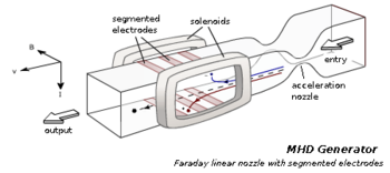
entry - an inlet for supplying a working fluid ( ionized gas );
acceleration nozzle - nozzle to increase the speed of the working fluid;
solenoids - solenoids for creating a magnetic field ;
segmented electrodes - electrodes divided into segments to reduce the Hall effect ;
output - the outlet for the output of the working fluid;
the red line is the direction of motion of positively charged particles ;
blue line - the direction of movement of negatively charged particles;
B - magnetic induction ;
I is the electric current ;
v is the speed of the working fluid
Magnetohydrodynamic generator, MHD generator - a power plant in which the energy of a working fluid (liquid or gaseous electrically conductive medium) moving in a magnetic field is converted directly into electrical energy .
Name Origin
In the MHD generator, there is a direct conversion of the mechanical energy of a moving medium into electrical energy. The motion of such media is described by magnetic dynamics (MHD), which gave the name to the device.
Principle of Operation
The principle of operation of the MHD generator, like a conventional machine generator , is based on the phenomenon of electromagnetic induction , that is, on the occurrence of a current in a conductor crossing the magnetic field lines . Unlike machine generators, the conductor in the MHD generator is the working fluid itself.
The working fluid moves across the magnetic field, and under the influence of the magnetic field, oppositely directed flows of charge carriers of opposite signs arise.
A charged particle is affected by the Lorentz force .

The working medium of the MHD generator can be the following media:
- electrolytes ;
- liquid metals;
- plasma (ionized gas).
The first MHD generators used electrically conductive liquids (electrolytes) as a working fluid. Currently, a plasma is used in which charge carriers are mainly free electrons and positive ions . Under the influence of a magnetic field, charge carriers deviate from the trajectory along which the gas would move in the absence of a field. In this case, a Hall field can arise in a strong magnetic field (see the Hall effect ), an electric field formed as a result of collisions and displacements of charged particles in a plane perpendicular to the magnetic field.
MHD pump
MHD generators have the property of reversibility. When an electric voltage is applied to the electrodes, a force will act on the electrically conductive medium, like a conductor with a current in a magnetic field. This force can be used to pump conductive liquids and gases.
Device
The MHD generator consists of a channel through which the working fluid (usually plasma ) moves, a system of magnets to create a magnetic field and electrodes that divert the received energy. As magnets can be used electromagnets or permanent magnets , as well as other sources of magnetic field.
A gas is capable of conducting (see electrical conductivity ) an electric current when heated to a temperature of thermal ionization of about 10,000 K. To reduce this temperature to 2200–2700 K, additives containing alkali metals are introduced into the heated gas. For example, the introduction of 1% potassium in the form of potash allows you to increase the conductivity tens of times. Without additives, at temperatures of 2200–2700 K, gas is a low-temperature plasma and conducts current worse than water.
Unlike a MHD generator with a liquid working fluid, where electricity is generated only by converting part of the kinetic or potential energy of the flow at a constant temperature, three modes are fundamentally possible in MHD generators with a gas working fluid:
- with the preservation of temperature and a decrease in kinetic energy;
- with conservation of kinetic energy and temperature reduction;
- with a decrease in both temperature and kinetic energy.
Description of the MHD generator:
- fuel, oxidizing agent and additives are fed into the combustion chamber;
- fuel burns and combustion products are formed - gases;
- gases pass through the nozzle , expand and increase their speed to supersonic ;
- gases enter a chamber through which a magnetic field is passed, and electrodes are installed in the walls of which;
- charged particles from an ionized gas, being under the influence of a magnetic field, deviate from the original trajectory under the action of the Lorentz force and rush to the electrodes;
- an electric current arises between the electrodes.
Classification
Classification by duration [1] :
- with a long working time;
- short-term action;
- impulse;
- explosive.
Heat sources in MHD generators can be:
- jet engines ;
- nuclear reactors ;
- heat exchangers .
As working fluids in MHD generators can be used:
- combustion products of fossil fuels ;
- inert gases with additives of alkali metals (or their salts);
- alkali metal vapors;
- two-phase mixtures of vapors and liquid alkali metals;
- liquid metals and electrolytes .
MHD generators are distinguished by the type of duty cycle:
- with an open cycle . The working fluid (combustion products) is mixed with additives (alkali metals), passes through the working chamber of the MHD generator, is cleaned of additives and emitted into the atmosphere;
- with a closed cycle . The working fluid is supplied to the heat exchanger (receives the thermal energy generated during fuel combustion), enters the working chamber of the MHD generator, passes through the compressor, and, closing the cycle, returns to the heat exchanger.
According to the method of electricity removal, MHD generators are distinguished:
- conductive - generating a constant or pulsating current (depending on the magnitude of the change in the magnetic field or the velocity of the working fluid). An electric current arises in a working fluid flowing through a transverse magnetic field. The current is closed to the external circuit through removable electrodes mounted on the side walls of the channel;
- induction - generating alternating current. In such MHD generators, there are no electrodes, and the creation of a magnetic field traveling along the channel is required.
In shape, the channels in MHD generators can be:
- linear (in conduction and induction generators);
- disk and coaxial Hall (in conductive generators);
- radial (in induction generators).
The design and method of connecting the electrodes distinguish the following MHD generators:
- Faraday generator . The electrodes are solid or divided into sections. Partitioning is performed to reduce current circulation along the channel and through the electrodes (to reduce the Hall effect). As a result, charge carriers move perpendicular to the channel axis to the electrodes and to the load. The larger the Hall effect, the more sections the electrodes need to be divided, and each pair of electrodes must have its own load, which greatly complicates the installation design;
- Hall generator . Electrodes are located opposite each other and are short-circuited. The voltage is removed along the channel due to the presence of the Hall field. The use of such MHD generators is most advantageous in high magnetic fields. Due to the presence of a longitudinal electric field, it is possible to obtain a significant voltage at the output of the generator;
- serial generator . The electrodes are connected diagonally.
Since the 1970s, the most widely used are linear MHD generators based on the products of combustion of fossil fuels with alkali metal additives operating on an open cycle.
History of invention
The idea of using a liquid conductor was first put forward by Michael Faraday in 1832. He proved that an electric current arises in a moving conductor under the influence of a magnetic field . In 1832, Faraday and his assistants lowered two copper sheets from the Waterloo bridge into the water of the River Thames . The sheets were connected by wires to the galvanometer . It was expected that the waters of the river flowing from west to east, the moving conductor and the Earth's magnetic field, will create an electric current, which is recorded by a galvanometer. The experience failed. Possible causes of failure include low water conductivity and low magnitude of the Earth's magnetic field .
Later, in 1851, the English scientist Wollaston was able to measure the EMF induced by tidal waves in the English Channel , but the lack of the necessary knowledge of the electrophysical properties of liquids and gases slowed down the use of the described effects in practice for a long time.
In subsequent years, research developed in two main areas:
- using the effect of induction of EMF to measure the speed of a moving electrically conductive medium (for example, in flow meters );
- electric power generation.
Although the first patents for the generation of electricity by an MHD generator using ionized gas of energy were issued back in 1907-1910, the designs described in them were unrealizable in practice. Then there were no materials capable of working in a gaseous environment at a temperature of 2500-3000 ° C.
The development of MHD generators became possible after the creation of a theoretical and experimental base for the study of magnetic hydrodynamics . The basic laws of MHD were discovered in 1944 by the Swedish scientist Hannes Alfvén when studying the behavior of cosmic plasma (plasma filling the interstellar space) in a magnetic field.
The first working MHD generator was built only in the 1950s thanks to the development of the theory of magnetic hydrodynamics and plasma physics , research in the field of high temperature physics and the creation by this time of heat-resistant materials, then used primarily in rocketry.
A plasma source with a temperature of 3000 K in the first MHD generator built in the USA in 1959 was a plasmatron operating on argon with an alkali metal additive to increase the degree of gas ionization . The generator power was 11.5 kW . By the mid-1960s, the capacity of MHD generators for combustion products was increased by 32 MW each (Mark-V, USA).
In the USSR, the first laboratory facility "U-02", which operated on natural fuel, was created in 1965 . In 1971, the U-25 experimental industrial power plant was launched, with an estimated capacity of 20-25 MW .
U-25 worked on natural gas combustion products with the addition of K 2 CO 3 as an ionizing additive, the flow temperature was about 3000 K. The installation had two circuits:
- primary, open, in which the conversion of heat of combustion products into electrical energy occurs in the MHD generator;
- secondary, closed - steam-power circuit using the heat of combustion products outside the channel of the MHD generator.
The U-25 electrical equipment consisted of an MHD generator and an inverter installation assembled on mercury ignitrons .
In Russia, an industrial MHD generator was built in Novomichurinsk, Ryazan Region, where a MHDES was specially built near the Ryazan State District Power Plant. However, the generator was never put into operation. Since the beginning of the 1990s, the work was completely phased out, and the MHD power station, without the MHD generator, operating as a conventional thermal power station, after several transformations was eventually connected to the Ryazan state district power station.
In the course of the Khibiny geophysical experiment in the mid-1970s in the USSR, the pulsed MHD generator with a maximum power of 100 MW , a current of 20 KA, and an operating time of about 10 s was used in the USSR for electro-sensing of the earth's crust [1] .
Features
Power
The power of the MHD generator is proportional to the conductivity of the working fluid, the square of its speed and the square of the magnetic field . For a gaseous working fluid in the temperature range 2000–3000 K, the conductivity is proportional to the temperature in the 11–13th degree and inversely proportional to the square root of pressure.
Flow Rate
The flow rates in the MHD generator can be in a wide range - from subsonic to hypersonic, over 1900 m / s.
Magnetic field induction
Magnetic field induction is determined by the design of the magnets and is limited to about 2 T for magnets with steel and up to 6-8 T for superconducting magnetic systems.
Strengths and weaknesses
Advantages:
- lack of moving units and parts (no friction losses);
- the ability to increase the efficiency of power plants up to 65% (since the gas exhausted in the MHD generator is suitable for generating electricity by traditional methods);
- high power ( 2 GW or more [ specify ] ); an increase in power is achieved by increasing the volume of the installation and is practically unlimited, since with the increase in volume the role of undesirable surface processes (pollution, leakage currents) only decreases;
- high maneuverability;
- reduction of emissions of harmful substances contained in the exhaust gases, with an increase in efficiency.
Disadvantages:
- high demands on the materials of the electrodes and walls of the working chamber (withstanding temperatures of 2000–3000 K, resistance to chemically active and hot winds with a speed of 1000–2000 m / s.);
- harmful emissions (products of combustion and impurities (for example, cesium )).
In combination with steam power plants, the MHD generator allows you to get large power in one unit, up to 500-1000 MW.
Application
Theoretically, there are five areas of industrial application of MHD generators:
- thermal power plants with an MHD generator based on fuel combustion products (open cycle); such installations are the simplest and have the short term prospects for industrial applications;
- nuclear power plants with an inert gas MHD generator heated in a nuclear reactor (closed cycle); the prospects of this direction depend on the development of nuclear reactors with a working fluid temperature in excess of 2000 K;
- neutron-cycle fusion power plants (for example, D + 3 He → p + 4 He + 18.353 MeV ) with a high-temperature MHD generator;
- cycles with an MHD generator based on liquid metal, which are promising for nuclear energy and for special power plants of relatively low power;
- hypersonic aviation systems. (over max 4 [ specify ] ).
Power plants with an MHD generator can also be used as backup or emergency sources of energy in power systems, for on-board power systems for space technology, as power sources for various devices requiring high power for short periods of time (for example, for powering wind tunnel electric heaters , etc.) P.).
Despite the attractive prospects and rapid development of research in the field of MHD generators in the 1970s, devices based on them did not find wide industrial application. A stumbling block is the lack of materials for the walls of the generator and electrodes capable of working at emerging transcendental temperatures for quite a long time [2] .
Another problem is that MHD generators produce only direct current . Accordingly, powerful and economical inverters are needed [3] .
In television educational programs in physics, published in the USSR in the late 1980s, it was reported that an industrial MHD generator was launched and working in the Ryazan region, which was not true: it never worked. We are talking about the Ryazan state district power station-24. The development of the installation was carried out, but ran into certain [ specify ] problems. Ultimately, the creation of the MHD generator was canceled, and the steam boiler of the installation was commissioned in 1984 autonomously [4] . В установке предусматривалась МГД-часть мощностью 500 МВт и следующая за ней газотурбинная надстройка мощностью 300—310 МВт [5] . Последняя впоследствии была доведена отдельно [4] и введена в эксплуатацию 1 июня 2010 года [6] .
See also
- МГД-динамо
- Плазма
- Yamato 1
Notes
- ↑ 1 2 Олег Мамаев. Как из движения сделать электричество: МГД-генераторы // Наука и жизнь . — 2015. — № 8. — С. 72—80. — ISSN 0028-1263. — URL
- ↑ Конюшая Ю. П. МГД-генераторы // Открытия советских ученых. — М. : Московский рабочий, 1979.
- ↑ Когда станут реальностью плазменные генераторы электричества? . «Электрик Инфо» . «КМ онлайн» (28 июля 2013). Date of treatment May 28, 2016.
- ↑ 1 2 Березинец П. А., Доверман Г. И., Терешина Г. Е., Крючкова Т. И. Газотурбинная надстройка энергоблока мощностью 300 МВт ГРЭС-24 с газотурбинной установкой ГТЭ-110 (недоступная ссылка) . ОАО «ВТИ» – ЗАО «Оптсим-К», г. Москва. Дата обращения 28 мая 2016. Архивировано 23 июня 2016 года.
- ↑ МГД-установка Рязанской ГРЭС . Энциклопедия по машиностроению XXL .
- ↑ Рязанская ГРЭС . ПАО «Газпром», ОГК-2.
Literature
- Ашкинази Л. МГД-генератор // Квант, 1980. — № 11. — С. 2—8.
- Рыжкин В. Электростанции газотурбинные, парогазовые, атомные и с МГД-генераторами // Тепловые электрические станции, 1975. — Глава 25.
- Тамоян Г. С. Учебное пособие по курсу «Специальные электрические машины» — МГД-машины и устройства.
- Каулинг Т. Магнитная гидродинамика. М.: Изд-во МИР, 1964. — 80 с.
- Касьян А. Напряжение плазменного смерча или просто — о МГД-генераторе // Двигатель, 2005 — № 6.
- «Физика машин»
- «Живая наука»