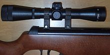
Optical sight - an optical device designed to accurately aim weapons at a target. It can also be used for observing terrain and for analytical calculation of distances to objects (if their sizes are known).
Content
History
The date of the invention of the telescope (the prototype of the modern optical sight) is considered to be 1608, when the Dutch spectacle master John Lippersgey demonstrated his invention in The Hague . Nevertheless, he was denied a patent for the telescope, because other masters, in particular Zachary Jansen from Middelburg and Jacob Metius from Alkmaar , already had specimens of telescopes, and the latter filed a request for a patent to the General States (Dutch Parliament) shortly after Lippersgey . Later studies showed that spyglasses were known back in 1605 [1] .
In 1745, the world's first optical sight was invented by the Russian mechanical scientist Andrei Konstantinovich Nartov , who worked in the Artillery Department in 1744-1746 [2] . In 1745 he was presented with a “Mathematical instrument with a promising telescope, with accessories and spirit level for quickly navigating from a battery or from the ground to the horizontal and olevation location shown to the target” [3] .
In 1850, I. Porro used “reversible” prisms on telescopes. Then the prismatic bent pipe was improved by E. Abbe , and then by K. Zeiss in Germany. Since the 1860s, gun telescopes have received significant use on hunting rifles abroad, and very little on military rifles . The first use of a rifle with a telescopic sight was found during the American Civil War (1861-1865) , where Colonel H. Berdan , the future American inventor, was the commander of the first sniper shooters. In the future, the first unregulated telescopes, having a large length of up to 80 cm (or more), gradually improved abroad, by the end of the 19th century, telescopes were arranged for setting sights in distance (high-altitude limb), optics were improved, and nodes were improved.
In 1880, August Fiedler of Stronsdorf (Austria-Hungary) created a modern type of optical sight [4] . Optical sights were of some importance in the Boer War of 1899-1902 . Only during the First World War, in connection with the new tactics of warfare introduced by foreign military experts, the development of sniping and the spread of optical sights took quick steps.
Up to 30% of the losses of Japanese troops during the battle of Okinawa are attributed to the marksmanship of American shooters equipped with optical sights [5] .
In 1949, Frederick Cales invented an optical sight with a variable magnification . In 1972, Kales patented multilayer optical illumination (AMV The modern optical sight has a device entirely developed abroad. The magnification (magnification) of optical sights is from 2X to 20X. Aperture , or clarity of the image of optical sights, should be at least 36, while at the beginning of the 20th century the aperture of the sights could be 100 or more.The variable magnification and aperture in optical sights allow you to increase the aperture by decreasing the magnification. atnosti and aperture invented Aymeric Laporte, and then a way to significantly improved the company's "Ger" and "Zeiss" . Currently, there are a plurality of optical sights with variable magnification and a change in the aperture ratio. The field of view or outlook of optical sights may vary depending on the destination and generally it varies from 2.5 ° with a tenfold increase to more than 20 ° with a double increase.The eye distance on rifles with high recoil is about 8 cm, on rifles with negligible recoil, for example, caliber 5.6 mm lateral og nya, can be reduced to 2-3 cm. The sights of the optical sights at first consisted of two thin threads crossing at a right angle.
In 1953, the electronic optical sight was adopted by the US Army to arm the Marxmanns - for the first time since the invention, the optical sight appeared in every infantry division [5] .
Modern optical sights allow you to move the eye along the optical axis of the eyepiece and away from it up to 4 mm without parallactic error in aiming. Modern optical sights have a caliper or side limb for horizontal installations. Such devices were invented by Kollat, Bush, Zeiss, etc. The weight and dimensions of optical sights have not changed significantly since the beginning of the 20th century: the weight of modern sights is limited to a range of 150-900 g (correlates with resistance to recoil), and length lies between 200-500 mm.
Device
A lens is a system of two (or more) lenses. The larger the diameter of the lens, the more it collects light and provides a large aperture of the sight and a bright "picture" of the field of view.
The input (external) lens of the lens usually has a special antireflection coating , applied by spraying or other method. To an outside observer, it may appear orange, emerald green, blue or purple depending on the materials used. Glass processed in this way transmits light better, due to which the sight lens forms a more contrasting and lighter image.
A reversing system — usually a lens — is used to turn the inverted image created by the lens into a direct one.
Reticle - designed to accurately point the target at the weapon on which the sight is mounted. The reticle is located in one of the focal planes of the sight (objective or ocular) and therefore the image of the target and the reticle are as if in the same plane and are visible to the eye equally sharply. In the simplest case, the reticle looks like a cross or half cross and is made of wires or obtained by etching the pattern on a durable metal foil placed inside the sleeve. The pattern of the reticle can have a different configuration and is applied to a transparent plate inside the wrapping system or directly to the lens. In addition to the crosshairs, some sights have a rangefinder scale that allows you to calculate the distance to the target, if its size is known. The main advantage of an optical sight over a conventional, mechanical one is that you do not need to constantly refocus the eye in order to align on the same line and clearly see the target, front sight and slit of the rear sight when aiming, which allows you to see the reticle and target simultaneously and equally clearly.
Eyepiece - is a multi-lens design and is designed to view an enlarged direct image of the target and the reticle. The focal length is usually 50 ... 70 mm for rifle sights and more than 300 mm for pistol sights. To quickly and accurately fix the position of the eye in the zone of full visibility of the field of view of the sight, as well as to avoid glare and flare on the lens, a rubber eyecup is often put on the eyepiece. The eyepieces of the sights usually have a diopter ring to adjust the eyepiece to the sight of the shooter.
Removal of the exit pupil. The most important characteristic of both tactical and hunting optical sights is the removal (removal) of the exit pupil . To protect the shooter's eye when shooting with a shot and during a powerful recoil from a shot , sights with a pupil extension of at least 60 mm should be chosen. The minimum permissible lower limit of offset for a rifle scope is 40 mm [6] .
The input mechanism of vertical and horizontal corrections - is used for shooting weapons and combining the center of the aiming net with the point of impact of the bullet. The sight can have one of the varieties of the corrections input mechanism - constant - the rotation of the drums occurs once when shooting a weapon for a specific munition, after which further rotation of the drums for firing is no longer required, or tactical drums - when corrections are introduced for each shot. The corrections input drums are needed to adjust the bullet's hit point due to a change in shooting conditions: moving the grid vertically allows you to set the scope for shooting at targets at different distances. When the reticle is moved down, the barrel of the weapon “rises”, as it were, the bullet flies along a higher path and vice versa. By moving the reticle horizontally, it is possible to compensate for the drift of a bullet in a side wind, making side corrections also makes it easier to fire ahead of a moving target. A scale is plotted on the handwheel drums for entering corrections, and their rotation occurs with locking clicks. This allows you to accurately determine the adjustment parameters and, if necessary, return the settings of the sight to its original position “by ear”, without taking your eyes off the observation of the target. Turning the handwheel of corrections by one click leads to a shift of the aiming point and a shift of the reticle by a certain angle. The magnitude of this angle or shift of the aiming point is indicated in the technical characteristics of the sight and is often indicated directly on the corrections drums themselves. Unlike sights with a reticle in the focal plane of the lens, in sights with an reticle in the focal plane of the eyepiece, the movement of the aiming point occurs simultaneously with the movement of the reversing system and therefore it seems that the reticle is in place.
Illuminated reticle. Thin reticles can be poorly distinguishable at dusk or against the background of vegetation: for shooting with a lack of light, optical sights with a backlight are produced. In high-quality sights of this type, a brightness adjustment is necessarily provided so that a too bright luminous reticle does not obscure the target. Some models of sights have double grid illumination, most often red and green, which is especially convenient in deep twilight. Sometimes the backlight node is combined with the correction input node. In ancient and army sights, the grid was made of filaments on the principle of a spiral of an incandescent lamp - until recently, such elements could be seen in cash registers, displays at railway stations and ancient calculators where wire numbers glowed. The wire mesh appears black when the power is off and orange when the power is on. In modern sights, an LED is installed, which illuminates either the image of the entire reticle, or only its translucent central part, sometimes even just a point in the crosshairs of the reticle.
Sight body - is made of durable light alloys and combines all the nodes of the sight in a single design, which should provide high resistance of the systems and mechanisms of the sight to the effects of shock loads that occur during shooting [7] .
A light- shielding hood or anti-glare nozzle - an additional device, usually in the form of a cylinder or cone made of metal, plastic or hard rubber, is put on the front of the optical lens housing to prevent side (parasitic) rays from entering and subsequently reflecting from the objective lens. The lens hood provides masking of the shooter's location and a very clear image of the aiming objects even in bright sunlight. The lens hood usually has one more internal thread for attaching special filters (for example, thin honeycomb or slotted lens hoods) for more effective clipping of side lighting.
Features
Increase
Optical sights can be divided into two main groups:
- Sights with constant magnification. They differ in high aperture and potentially give a clearer image. There are no massive moving elements in their design (with the exception of lenses and a reticle of the reticle), their optical system consists of fewer lenses, which, no matter how perfect, still absorb light. Sights with a constant magnification are preferable if it is known exactly in what conditions and at what firing distances they will be used.
- Variable sights (pancratic). Sights with variable magnification are potentially darker, therefore their production requires better lenses, but such sights are also more universal, since they allow you to change the field of view, the angle of which is inversely proportional to the ratio: the greater the magnification, the smaller the field of view.
If the reticle is in the focal plane of the lens for a sight with variable magnification, the so-called the front plane, FFP, then with increasing magnification, visible dimensions and targets and the reticle are enlarged. At the sight with a reticle in the focal plane of the eyepiece, the so-called the rear plane, SFP, when changing the magnitude, only the target image grows, and the visible dimensions of the reticle and the thickness of its threads remain unchanged.
The choice of the magnification of the sight depends on which weapon for which purpose and in what conditions it is supposed to be used: for sports shooting at targets in a shooting gallery or for hunting, as well as on its variety. For shooting at short distances - up to 60 m - it is better to use sights with a small magnification (1.5: 4-6x). These sights are light, small in size, they allow you to shoot confidently quickly, sometimes even offhand, without careful aiming, possibly with two eyes open. Sights with a magnification of more than 6x are designed for shooting slowly, well aiming. Such sights should have high-quality optics - high aperture ratio, high light transmission of the optical system, high twilight number, high image contrast and accurate operation of correction mechanisms. And the first and second, regardless of the multiplicity, can have the illumination of the reticle. The disadvantage of all sights with a large magnification is the small field of view, which makes it difficult to search for targets at long distances and shoot close to moving targets. This drawback is partially deprived of panoramic sights - you can set the minimum magnification to quickly aim with two eyes open for firing at short distances or at a moving target. For ease of use, this is comparable to collimator sights, while retaining all the advantages of sights with a large magnification.
Parallax
The optical system of the sight is arranged in such a way that the image of the distant target is projected by the lens into the plane where the aim grid is located. Parallax in sights is called the mismatch of the plane of the target image formed by the lens with the plane of the reticle. This can be both the front focal plane (lens, FFP) and the rear focal plane (eyepiece, SFP). It is not difficult to notice parallax: in ancient times, when all sights had a reticle only in the focal plane of the lens, one could notice that when the eye was displaced perpendicular to the axis of the sight, the target image seemed to “float” relative to the center of the grid and the aim point “moved” from the target. For accurate shooting it is necessary, but without a skill it’s not easy enough - to be able to quickly find and hold the desired eye position exactly on the optical axis of the sight during aiming.
In modern sights, where the reticle is located in the rear focal plane (eyepiece), when the eye is shifted, the arrow from the optical axis of the sight does not noticeably shift the reticle. But, surprisingly, the parallax is also in them and it is just as easy to see, it only manifests itself in a completely different way - blurring of the aiming grid and the inability to see the image of the target and the aiming grid simultaneously and with the same sharpness if the target is not infinitely -Remote distance (usually in life there is shooting at distances somewhat less than infinity). To see both the target image and the reticle with equally high definition at an infinitely remote (small) distance, you need to make adjustments to the settings of the optical system of the sight for each specific firing range, changing the interfocal distance of the lens and eyepiece.
To eliminate parallax in high-end sights, there is a lens focusing mechanism that allows you to place the image from the lens exactly on the plane of the reticle. Usually, for this purpose, the entire lens system of the sight lens is moved or only its inner part located closer to the grid. There are two types of parallax detuning types - AO (Adjustable Objective) and SF (Side Focusing) [8] .
The first type (AO) : the parallax detuning ring is located directly on the rim of the sight lens (hence the name). The ring is marked with a scale indicating the focusing distance, usually in yards or meters (rarely). Parallax is eliminated by adjusting the lens to the desired division of the shooting distance. This method is more common in view of its unpretentiousness and ease of implementation, or more simply - a slight increase in the cost of sight with AO. But cheapness, as always, has a downside - it is impossible to twist the lens parallax detuning ring without changing the position of manufacture for shooting, which is not always convenient.
The second type (SF) : the parallax detuning mechanism is located on the side of the sight and it is often equipped with a huge helm, which serves for the convenience and smoothness of the parallax detuning, without changing the manufacture and position of the shooter's head and body when aiming.
Advantages
- the image of the target and the reticle is at the same distance from the eye, which allows you to clearly see them and reduces eye fatigue;
- the optical sight increases the size of the target, which allows precise guidance of weapons at remote and / or small targets;
- The optical sight collects a greater amount of light than the eye, which allows you to clearly see objects in low light. Some sights are additionally equipped with an illuminated reticle illumination device, which allows you to see it clearly against the background of a dark target;
- using the reticle, you can determine the angular dimensions of the target, which allows you to calculate the distance to it;
- with the help of an optical sight, it is possible to level the effect of light visual defects, including myopia , hyperopia and some types of astigmatism [9] , on the accuracy of shooting. Nevertheless, shooters with cataracts can not refuse glasses when shooting: they can be offered only general recommendations on the aiming technique and the selection of suitable optics.
Weaknesses
- The optical sight reduces the field of view, which makes it difficult to detect the target. When shooting with a telescopic sight, firing at a moving target is especially complicated;
- trembling hands and movement of the chest during breathing can significantly complicate aiming;
- when shooting using optics, the shooter often closes one eye, focusing on the image of the target. This creates a danger for the shooter, because with a closed eye he will not be able to notice the enemy if he appears from the side, outside the field of view of the optical sight (say, when the enemy performs patrol circumambulation ). Therefore, experienced shooters devote much time to disguising their position and aim, keeping both eyes open;
- at small distances (less than 20-30 m), the sight creates a blurry image and parallax appears (when the eye moves relative to the sight, the reticle moves relative to the target image), which reduces the accuracy of the aim. Some sights allow you to adjust them for firing at short distances;
- when shooting, the eye should be at a certain distance from the sight (as a rule, this distance is within 5-10 cm), otherwise distortions occur, the field of view decreases and there is a risk of eye injury due to recoil of the weapon. If the sight is equipped with a rubber eyecup, then the eye must be placed close to it.
- the shine of the lenses can unmask the position of the sniper.
- Optical sights can easily be detected by laser sniper detection systems.
- the use of an optical sight forces the sniper to keep his head a few centimeters higher, which significantly increases the risk of being killed.
- when using low-quality sights, a sniper may encounter the problem of fogging the glass and the formation of frost on the lenses. It is solved by blowing the tube with a dry inert gas (mixtures of nitrogen , argon, etc.): it is desirable that the procedure be carried out in the factory.
Reticle
The reticle is either a metal stencil (in the simplest case, two intersecting wires), or glass with a pattern printed on it. The reticle is located either in the first (located in the middle of the scope, the image is upside down), or in the second (located in the eyepiece, the image is straight) of the focal plane of the scope.
To aim a weapon at a target, it is necessary to combine the image of the target with the image of a certain part of the reticle (this can be a stump, crosshairs, corner, etc.). When shooting with special handwheels, the grid is moved, combining it with the midpoint of the hit. There are various reticles that are convenient in various situations:
Cross Grid
Allows you to accurately aim your weapon at a small and / or remote stationary target. Knowing the angular distance from the crosshairs to the thickening of the threads, you can estimate the angular dimensions of the target.
Stump Grid
Allows you to quickly aim your weapon at the target. Knowing the gap between the side lines, you can estimate the angular dimensions of the target.
Grid "PSO-1"
It was first used on the Soviet optical sight PSO-1 , now it is used on many sights, mainly produced in the CIS .
The grid allows you to accurately point your weapon at a small and / or remote stationary target and accurately determine its angular dimensions. It has an additional long-range scale that allows you to quickly determine the distance to a person standing at full height 1.7 m (there are versions designed for a different target height - 1.8 m). Additional sighting angles allow you to shoot at different distances without reconfiguring the sight.
One division of the scale is approximately 1/1000 radian, or simply one " thousandth ". The distance to an object in units of length is equal to its size in units of length times 1000 and divided by its angular size in thousandths. For example, if an object has a width of 0.7 m and an angular width of 4 thousandths, then the distance to it is 0.7⋅1000 / 4 = 175 m.
Mil-Dot Grid
Such a grid also allows you to accurately point the weapon at a small and / or remote stationary target and accurately determine the distance to the target. The angular distance between points on the grid is 1 mil . The angular dimensions of the points themselves are, as a rule, 0.25 miles, and the angular distance between the edges of neighboring points is 0.75 miles.
See also
- Aim
- Thousandth (angle)
- Collimator
Notes
- ↑ V.A. Gurikov. The history of the creation of the telescope. Historical and astronomical research, XV / Otv. ed. L.E. Maistrov - M., Science, 1980.
- ↑ Tsarev turner. Andrey Konstantinovich Nartov. Russian inventor. .
- ↑ Nartov Andrey Konstantinovich, creator of the world's first screw-cutting lathe with a mechanic. caliper, and another 30 inventions. - Russian Empire - For the first time in the world - Articles - Famous names . slavnyeimena.ru. Date of treatment January 26, 2019.
- ↑ Important Dates in Gun History, Compiled and Researched by the American Firearms Institute . Americanfirearms.org. Date of treatment November 26, 2010. Archived November 18, 2010.
- ↑ 1 2 Sniperscopes . // Military Review . - October 1950. - Vol. 30 - No. 7 - P. 63.
- ↑ Solodilov K.E. Military optical-mechanical devices. - M .: State Publishing House of the defense industry, 1940. - S. 154. - 262 p.
- ↑ Optics. How are optical sights arranged and to whom to believe?
- ↑ Types of parallax adjustment
- ↑ Optical sight for visual impairment
Literature
- Potapov Alexey. Army optical sights // The Art of a sniper . - “Fair-Press”, 2005. - 10,000 copies. - ISBN 5-8183-0360-8 .
- Davydov B., Savenko S. Soviet optical sights of the 1920s-1940s (Russian) // World of weapons: magazine. - 2005. - March ( t. 06 , No. 03 ). - S. 18-25 . - ISSN 1607-2009 .
- Davydov B., Savenko S. Soviet optical sights of the 1920s-1940s (Russian) // World of weapons: magazine. - 2005. - April ( t. 07 , No. 04 ). - S. 16-23 . - ISSN 1607-2009 .
- Davydov B., Savenko S. Soviet optical sights of the 1920s-1940s (Russian) // World of weapons: magazine. - 2005. - May ( t. 08 , No. 05 ). - S. 52-59 . - ISSN 1607-2009 .
- Davydov B., Savenko S. Soviet optical sights of the 1920s-1940s (Russian) // World of weapons: magazine. - 2005. - June ( t. 09 , No. 06 ). - S. 36-45 . - ISSN 1607-2009 .
- Valnev V., Martino K. Sights (rus.) // Magnum: magazine. - 2000. - T. 15 , No. 03 . - S. 55 .