
A steam engine is a heat engine of external combustion that converts the energy of water vapor into the mechanical work of the reciprocating motion of the piston , and then into the rotational motion of the shaft . In a broader sense, a steam engine is any external combustion engine that converts steam energy into mechanical work.
The first steam engine was built in the XVII century. Papen also represented a cylinder with a piston, which was raised by the action of steam, and dropped by atmospheric pressure after condensation of the spent steam. In the same principle, vacuum steam engines of Severi and Newcomen were built in 1705 for pumping water from mines. Significant improvements to the vacuum steam engine were made by James Watt in 1769 . Further significant improvement of the steam engine (the use of high pressure steam instead of vacuum on the move) was made by the American Oliver Evans in 1786 and the Englishman Richard Trevitik in 1800 .
In Russia, the first operating steam engine was built in 1766 according to the project of Ivan Polzunov , proposed by him in 1763 . Polzunov’s machine had two cylinders with pistons, it worked continuously, and all actions in it took place automatically. But I. Polzunov did not have to see his invention in his work: he died on May 27, 1766, and his car was put into operation at the Barnaul plant only in the summer [1] . After a couple of months, due to a breakdown, it ceased to function and was subsequently dismantled.
Principle of Operation
A steam boiler is required to drive a steam engine. The expanding steam presses on the piston or on the blades of the steam turbine , the movement of which is transmitted to other mechanical parts.
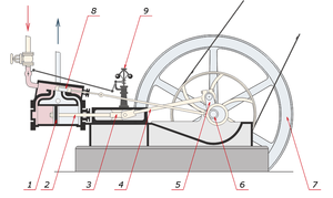
The principle of operation of a steam engine is shown in Fig. The operation of the piston 1 by means of the rod 2, slide 3, connecting rod 4 and crank 5 is transmitted to the main shaft 6, carrying the flywheel 7, which serves to reduce the uneven rotation of the shaft. An eccentric sitting on the main shaft, using an eccentric traction, drives a spool 8, which controls the steam inlet in the cylinder cavity. Steam from the cylinder is released into the atmosphere or enters the condenser . To maintain a constant number of shaft revolutions under a changing load, steam engines are equipped with a centrifugal regulator 9, which automatically changes the cross section of the passage of steam entering the steam engine ( throttle regulation , shown in the figure), or the moment of filling cut-off ( quantitative regulation ).
The piston forms one or two cavities of variable volume in the cylinder of the steam engine, in which the processes of compression and expansion take place, as shown in Fig. curves of pressure p versus volume V of the indicated cavities.
These curves form a closed line in accordance with the thermal cycle along which the steam engine operates between pressures p 1 and p 2 , as well as volumes V 1 and V 2 . The primary piston engine is designed to convert the potential thermal energy (pressure) of water vapor into mechanical work. P.'s working process of m is caused by periodic changes in the vapor pressure in the cavities of its cylinder, the volume of which changes during the reciprocating motion of the piston. The steam entering the cylinder of the steam engine expands and moves the piston. The reciprocating movement of the piston is converted using the crank mechanism into the rotational movement of the shaft. Steam inlet and outlet are carried out by a steam distribution system. To reduce heat loss, the cylinders of the steam engine are surrounded by a steam jacket.
The moments of the beginning and end of the processes of expansion and compression of steam give four main points of the real cycle of the steam engine: volume V e , determined by point 1 of the beginning or pre-intake; the volume of the end of the inlet or filling E , determined by point 2 of the cutoff of the filling; the volume of pre-release or end of expansion V a , determined by point 3 of pre-release; the compression volume V c determined by point 4 of the beginning of compression. In a real steam engine, the listed volumes are recorded by steam distribution authorities .
Efficiency
The coefficient of performance (COP) of a heat engine can be defined as the ratio of the useful mechanical work to the expended amount of heat contained in the fuel . The rest of the energy released into the environment in the form of heat .
The efficiency of the heat engine is
- ,
- Where
- W out - mechanical work, J;
- Q in - spent amount of heat, J.
- Where
A heat engine cannot have an efficiency greater than that of the Carnot cycle , in which the amount of heat is transferred from a heater with a high temperature to a refrigerator with a low temperature. The efficiency of an ideal Carnot heat engine depends solely on the temperature difference, and the absolute thermodynamic temperature is used in the calculations. Therefore, for steam engines, the highest possible temperature T 1 at the beginning of the cycle (achieved, for example, using superheating ) and the lowest possible temperature T 2 at the end of the cycle (for example, using a capacitor ) are required:
A steam engine that releases steam into the atmosphere will have a practical efficiency (including a boiler) from 1 to 8%, but an engine with a condenser and expansion of the flow part can improve efficiency up to 25% and even more. A thermal power plant with a superheater and regenerative water heating can achieve an efficiency of 30–42%. Combined cycle combined cycle plants in which the energy of the fuel is first used to drive a gas turbine and then for a steam turbine can achieve an efficiency of 50-60%. At a CHP plant, efficiency is improved through the use of partially exhausted steam for heating and production needs. In this case, up to 90% of the fuel energy is used and only 10% is scattered uselessly in the atmosphere.
Such differences in efficiency occur due to the characteristics of the thermodynamic cycle of steam engines. For example, the greatest heating load falls on the winter period, so the efficiency of the CHPP increases in winter.
One of the reasons for the decrease in efficiency is that the average vapor temperature in the condenser is slightly higher than the ambient temperature (the so-called temperature head is formed ). The average temperature head can be reduced through the use of multi-pass capacitors. The use of economizers, regenerative air heaters, and other means of optimizing the steam cycle also increases the efficiency.
In steam engines, a very important property is that isothermal expansion and contraction occur at constant pressure, specifically, at the pressure of the steam coming from the boiler. Therefore, the heat exchanger can be of any size, and the temperature difference between the working fluid and the cooler or heater is almost 1 degree. As a result, heat loss can be minimized. For comparison, the temperature difference between the heater or cooler and the working fluid in stirling can reach 100 ° C.
Advantages and disadvantages
The main advantage of steam engines as external combustion engines is that because of the separation of the boiler from the steam engine, almost any type of fuel (heat source) can be used - from dung to uranium . This distinguishes them from internal combustion engines, each type of which requires the use of a certain type of fuel. This advantage is most noticeable when using nuclear energy, because a nuclear reactor is not able to generate mechanical energy, but produces only heat, which is used to generate steam that drives steam engines (usually steam turbines). In addition, there are other sources of heat that cannot be used in internal combustion engines, for example, solar energy . An interesting direction is the use of energy of the temperature difference of the oceans at different depths.
Other types of external combustion engines, such as the Stirling engine , which can provide very high efficiency, but have significantly greater weight and dimensions than modern types of steam engines, also have similar properties.
Steam locomotives perform well at high altitudes, because their efficiency does not fall, but, on the contrary, increases due to low atmospheric pressure. Steam locomotives are still used in the mountainous regions of Latin America and China, despite the fact that in the lowlands they have long been replaced by more modern types of locomotives.
In Switzerland (Brienz Rothhorn) and Austria (Schafberg Bahn), new dry steam locomotives have proven their worth. This type of locomotive was developed on the basis of 1930s Swiss Locomotive and Machine Works (SLM) models, with many modern improvements, such as the use of roller bearings, modern thermal insulation, light oil burning as fuel, improved steam lines, etc. As a result, these locomotives have 60% less fuel consumption and significantly lower maintenance requirements. [ specify ] . The economic qualities of such locomotives are comparable to modern diesel locomotives and electric locomotives. [ specify ] .
In addition, steam locomotives are much lighter than diesel and electric, which is especially true for mountain railways. A feature of steam engines is that they do not need a transmission , transferring force directly to the wheels.
Invention and Development
The first known device, driven by steam, was described by Heron of Alexandria in the first century . Steam tangentially released from nozzles mounted on a ball made the latter rotate.
A real steam turbine was invented much later, in medieval Egypt , by a Turkish astronomer, physicist and engineer of the 16th century Takiyuddin al-Shami . He proposed a method for rotating the spit by means of a steam flow directed to the blades fixed along the wheel rim.
A similar machine was proposed in 1629 by an Italian engineer Giovanni Branca to rotate a cylindrical anchor device, which in turn raised and released a couple of pestles in the mortars . The steam flow in these early steam turbines was not concentrated, and most of its energy was dissipated in all directions, resulting in significant energy losses.
The steam engine was created by Spanish inventor Jeronimo Ajans de Beaumont , whose inventions influenced the patent of the Englishman T. Severi (see below). The principle of operation and application of steam engines were also described in 1655 by the Englishman Edward Somerset ; in 1663 he published the project and installed a steam-driven device for lifting water on the wall of the Great Tower in Raglan Castle (the recesses in the wall where the engine was installed were still noticeable in the 19th century ). However, no one was willing to risk money for this new revolutionary concept, and the steam engine remained undeveloped.
One of the experiments of the French physicist and inventor Denis Papin was to create a vacuum in a closed cylinder. In the mid-1670s in Paris , in collaboration with the Dutch physicist Huygens, he worked on a machine that displaced air from a cylinder by exploding gunpowder in it. Seeing the incompleteness of the vacuum created by this, Papen, after arriving in England in 1680, created a variant of the same cylinder, in which he received a more complete vacuum using boiling water, which condensed in the cylinder. Thus, he was able to lift the load attached to the piston with a rope thrown over the pulley . The system worked only as a demonstration model: to repeat the process, the entire apparatus had to be dismantled and reassembled. Papen quickly realized that to automate the cycle, steam had to be produced separately in the boiler. Therefore, Papen is considered the inventor of the steam boiler , thus paving the way for the Newcomen steam engine . However, he did not propose the design of an existing steam engine. Papen also designed a boat propelled by a wheel with reactive power in a combination of the concepts of Taki ad-Din and Severi; he is also credited with the invention of many important devices, for example, a safety valve .
None of the described devices was actually used as a means of solving useful problems. The first steam engine used in production was a "fire engine", designed by the British military engineer Thomas Severi in 1698 . Severi received a patent for his device in the same year. It was a steam pump without a piston, and, obviously, not very effective, since the heat of the steam was lost every time during the cooling of the container, and quite dangerous in operation, because of the high pressure of the steam, the tanks and pipelines of the pump sometimes exploded. Since this device could be used both for the rotation of the wheels of a water mill and for pumping water from the mines, the inventor called him "a friend of the miner."
In 1712, the English blacksmith Thomas Newcomen demonstrated his "atmospheric (vacuum) engine . " It was Severi's advanced steam engine, in which Newcomen used a cylinder with a piston and significantly reduced the working pressure of the steam. The first use of the Newcomen engine was pumping water from a deep mine. In the shaft pump, the beam was connected to a rod that descended into the shaft toward the pump chamber. The reciprocating thrust was transmitted to the piston of the pump, which supplied water upward. It was the Newcomen pump that became the first steam engine to receive wide practical application.
In 1720, the German physicist invented a two-cylinder high-pressure steam engine in which the working stroke is not achieved by low vacuum pressure, which is formed after water is injected into a cylinder with hot water vapor, as in vacuum engines, but by high pressure of hot water vapor . Waste steam is discharged into the atmosphere. But high-pressure machines were built only 80 years later, at the beginning of the 19th century, by American Oliver Evans and Englishman Richard Trevitik .
In 1763, mechanic I.I. Polzunov designed the first two-cylinder vacuum steam engine in Russia for actuating blower bellows at the Barnaul Kolyvano-Voskresensky factories, which was built in 1764 .
In 1765, James Watt made a separate capacitor to increase the efficiency of Newcomen's vacuum engine. The engine was still vacuum.
В 1781 году Джеймс Уатт запатентовал вакуумную паровую машину с кривошипно-шатунным механизмом , которая производила непрерывное вращательное движение вала (в отличие от поступательного движения в вакуумном двигателе водоподъёмного насоса Ньюкомена). Двигатель всё ещё оставался вакуумным, но вакуумный двигатель Уатта с кривошипно-шатунным механизмом , мощностью 10 лошадиных сил , стало возможным, при наличии каменного угля и воды, устанавливать и использовать в любом месте для любой цели. С вакуумным двигателем Уатта принято связывать начало промышленной революции в Англии .
Примечательно, что первой известной автоматической системой управления была система регулирования скорости пара, установленный на паровом двигателе Уатта в 1775 году; почти век спустя Джеймс Клерк Максвелл описал первую математическую модель автоматизации.
Дальнейшим повышением эффективности парового двигателя было применение пара высокого давления американцем Оливером Эвансом и англичанином Ричардом Тревитиком .
В 1786 году Эванс попытался было запатентовать обычный паровой автомобиль , в котором приводом служила паровая машина высокого давления, но патентное управление отказало Эвансу, посчитав его идею нелепой фантазией. Позже Эванс изготовил в общей сложности около полусотни подобных машин, большая часть которых использовалась для привода насосных установок.
Ричард Тревитик , инициатор создания и применения стационарных машин, работающих при высоких давлениях (получил в 1800 г. патент на «машину высокого давления»), освоил на практике цилиндрические паровые (так называемые «корнваллийские») котлы (1815). С 1797 строил модели паровых повозок, а в 1801 начал строить оригиналы повозок, последняя из которых прошла успешные испытания в Корнуэлле и Лондоне (1802—1803).
В 1801 году Ричард Тревитик построил первый в истории паровоз « Puffing Devil », затем в 1802 году паровоз « Coalbrookdale » для одноимённой угольной компании.
Тревитик успешно строил промышленные однотактовые двигатели высокого давления, известные как «корнуэльские двигатели». Они работали с давлением 50 фунтов на квадратный дюйм , или 345 кПа (3,405 атмосферы). Однако с увеличением давления возникала и большая опасность взрывов в машинах и котлах, что приводило вначале к многочисленным авариям. С этой точки зрения наиболее важным элементом машины высокого давления был предохранительный клапан, который выпускал лишнее давление. Надёжная и безопасная эксплуатация началась только с накоплением опыта и стандартизацией процедур сооружения, эксплуатации и обслуживания оборудования. Множество вакуумных двигателей, построенных ранее по схеме Джеймса Уатта, после изобретения Эванса и Тревитика были перестроены по схеме «корнуэльского двигателя» высокого давления.
В 1769 году французский изобретатель Николя-Жозеф Кюньо продемонстрировал первое действующее самоходное паровое транспортное средство : « fardier à vapeur » (паровую телегу). Возможно, его изобретение можно считать первым автомобилем . Самоходный паровой трактор оказался очень полезным в качестве мобильного источника механической энергии, приводившего в движение другие сельскохозяйственные машины: молотилки , прессы и др. В 1788 году пароход , построенный Джоном Фитчем, уже осуществлял регулярное сообщение по реке Делавэр между Филадельфией (штат Пенсильвания) и Берлингтоном (штат Нью-Йорк ). Он поднимал на борт 30 пассажиров и шёл со скоростью 7—8 узлов . 21 февраля 1804 года на металлургическом заводе Пенидаррен в городе Мертир-Тидвил в Южном Уэльсе демонстрировался первый самоходный железнодорожный паровой локомотив , построенный Ричардом Тревитиком.
В 1824 году французский учёный и инженер Сади Карно в своём сочинении «О движущей силе огня и о машинах, способных развивать эту силу» впервые описал цикл работы термодинамической системы , позже названный его именем [2] [3] .
Следует отметить, что распространение парового двигателя шло постепенно: механизмы, использующие водную и ветряную энергию, ещё долго конкурировали с паровыми машинами. В частности, до 1870 года в Соединённых Штатах большинство фабрик использовали энергию водяных турбин, а не паровых двигателей [4] .
Classification
Паровые машины разделяются:
- по способу действия пара на машины с расширением и без него, причем первые считаются наиболее экономичными
- по используемому пару
- низкого давления (до 12 кг/см²)
- среднего давления (до 60 кг/см²)
- высокого давления (свыше 60 кг/см²)
- по числу оборотов вала
- тихоходные (до 50 об/мин, как на колёсных пароходах )
- быстроходные.
- по давлению выпускаемого пара
- на конденсационные (давление в конденсаторе 0,1—0,2 ата)
- выхлопные (с давлением 1,1—1,2 ата)
- теплофикационные с отбором пара на нагревательные цели или для паровых турбин давлением от 1,2 ата до 60 ата в зависимости от назначения отбора (отопление, регенерация, технологические процессы, срабатывание высоких перепадов в предвключённых паровых турбинах ).
- По расположению цилиндров
- горизонтальные
- наклонные
- вертикальные
- по числу цилиндров
- одноцилиндровые
- многоцилиндровые
- сдвоенные, строенные и т. д., в которых каждый цилиндр питается свежим паром
- паровые машины многократного расширения, в которых пар последовательно расширяется в 2, 3, 4 цилиндрах возрастающего объёма, переходя из цилиндра в цилиндр через т. н. ресиверы (коллекторы).
По типу передаточного механизма паровые машины многократного расширения делятся на тандем-машины (рис. 4) и компаунд-машины (рис. 5). Особую группу составляют прямоточные паровые машины , в которых выпуск пара из полости цилиндра осуществляется кромкой поршня.
По их применению: на стационарные машины и нестационарные (в том числе передвижные), устанавливаемые на различные типы транспортных средств .
Стационарные паровые машины могут быть разделены на два типа по режиму использования:
- Машины с переменным режимом, к которым относятся машины металлопрокатных станов , паровые лебёдки и подобные устройства, которые должны часто останавливаться и менять направление вращения.
- Силовые машины, которые редко останавливаются и не должны менять направление вращения. Они включают энергетические двигатели на электростанциях , а также промышленные двигатели, использовавшиеся на заводах, фабриках и на кабельных железных дорогах до широкого распространения электрической тяги. Двигатели малой мощности используются на судовых моделях и в специальных устройствах.
Паровая лебёдка в сущности является стационарным двигателем, но установлена на опорной раме, чтобы её можно было перемещать. Она может быть закреплена тросом за якорь и передвинута собственной тягой на новое место.
Паровые машины с возвратно-поступательным движением
Двигатели с возвратно-поступательным движением используют энергию пара для перемещения поршня в герметичной камере или цилиндре. Возвратно-поступательное действие поршня может быть механически преобразовано в линейное движение поршневых насосов или во вращательное движение для привода вращающихся частей станков или колёс транспортных средств.
Вакуумные машины
Ранние паровые машины назывались вначале « огневыми машинами», а также « атмосферными » или «конденсирующими» двигателями Уатта. Они работали на вакуумном принципе и поэтому известны также как «вакуумные двигатели». Такие машины работали для привода поршневых насосов , во всяком случае, нет никаких свидетельств о том, что они использовались в иных целях. При работе паровой машины вакуумного типа в начале такта пар низкого давления впускается в рабочую камеру или цилиндр. Впускной клапан после этого закрывается, и пар охлаждается, конденсируясь. В двигателе Ньюкомена охлаждающая вода распыляется непосредственно в цилиндр, и конденсат сбегает в сборник конденсата. Таким образом создаётся вакуум в цилиндре. Атмосферное давление в верхней части цилиндра давит на поршень, и вызывает его перемещение вниз, то есть рабочий ход.
Поршень связан цепью с концом большого коромысла, вращающегося вокруг своей середины. Насос под нагрузкой связан цепью с противоположным концом коромысла, которое под действием насоса возвращает поршень к верхней части цилиндра силой гравитации . Так происходит обратный ход. Давление пара низкое и не может противодействовать движению поршня. [five]
Постоянное охлаждение и повторное нагревание рабочего цилиндра машины было очень расточительным и неэффективным, тем не менее, эти паровые машины позволяли откачивать воду с большей глубины, чем это было возможно до их появления. В 1774 году появилась версия паровой машины, созданная Уаттом в сотрудничестве с Мэттью Боултоном, основным нововведением которой стало вынесение процесса конденсации в специальную отдельную камеру ( конденсатор ). Эта камера помещалась в ванну с холодной водой, и соединялась с цилиндром трубкой, перекрывающейся клапаном. К конденсационной камере была присоединена специальная небольшая вакуумная помпа (прообраз конденсатного насоса), приводимая в движение коромыслом и служащая для удаления конденсата из конденсатора. Образовавшаяся горячая вода подавалась специальным насосом (прообразом питательного насоса) обратно в котёл. Ещё одним радикальным нововведением стало закрытие верхнего конца рабочего цилиндра, в верхней части которого теперь находился пар низкого давления. Этот же пар присутствовал в двойной рубашке цилиндра, поддерживая его постоянную температуру. Во время движения поршня вверх этот пар по специальным трубкам передавался в нижнюю часть цилиндра, для того, чтобы подвергнуться конденсации во время следующего такта. Машина, по сути, перестала быть «атмосферной», и её мощность теперь зависела от разницы давлений между паром низкого давления и тем вакуумом, который удавалось получить.
В паровой машине Ньюкомена смазка поршня осуществлялась небольшим количеством налитой на него сверху воды, в машине Уатта это стало невозможным, поскольку в верхней части цилиндра теперь находился пар, пришлось перейти на смазку смесью тавота и нефти. Такая же смазка использовалась в сальнике штока цилиндра. [one]
Вакуумные паровые машины, несмотря на очевидные ограничения их эффективности, были относительно безопасны, использовали пар низкого давления, что вполне соответствовало общему невысокому уровню котельных технологий XVIII века . Мощность машины ограничивалась низким давлением пара, размерами цилиндра, скоростью сгорания топлива и испарения воды в котле, а также размерами конденсатора. Максимальный теоретический КПД был ограничен относительно малой разницей температур по обе стороны поршня; это делало вакуумные машины, предназначенные для промышленного использования, слишком большими и дорогими.
Приблизительно в 1811 году Ричард Тревитик усовершенствовал машину Уатта. Давление пара над поршнем достигло 275 кПа (2,8 атмосферы), и именно оно давало основную мощность для совершения рабочего хода; кроме того, был существенно усовершенствован конденсатор. Такие машины получили название , и строились вплоть до 1890-х годов. Множество старых машин Уатта было реконструировано до этого уровня. Некоторые из корнуэльских машин имели весьма большой размер.
Паровые машины высокого давления
В паровых машинах пар поступает из котла в рабочую камеру цилиндра, где расширяется, оказывая давление на поршень и совершая полезную работу. После этого расширенный пар может выпускаться в атмосферу или поступать в конденсатор. Важное отличие машин высокого давления от вакуумных состоит в том, что давление отработанного пара превышает атмосферное или равно ему, то есть вакуум не создаётся. Отработанный пар обычно имел давление выше атмосферного и часто выбрасывался в дымовую трубу , что позволяло увеличить тягу котла.
Важность увеличения давления пара состоит в том, что при этом он приобретает более высокую температуру. Таким образом, паровая машина высокого давления работает при большей разнице температур чем та, которую можно достичь в вакуумных машинах. После того, как машины высокого давления заменили вакуумные, они стали основой для дальнейшего развития и совершенствования всех возвратно-поступательных паровых машин. Однако то давление, которое считалось в 1800 году высоким (275—345 кПа), сейчас рассматривается как очень низкое — давление в современных паровых котлах в десятки раз выше.
Дополнительное преимущество машин высокого давления состоит в том, что они намного меньше при заданном уровне мощности, и соответственно, существенно менее дорогие. Кроме того, такая паровая машина может быть достаточно лёгкой и компактной, чтобы использоваться на транспортных средствах. Возникший в результате паровой транспорт (паровозы, пароходы) революционизировал коммерческие и пассажирские перевозки, военную стратегию, и вообще затронул практически каждый аспект общественной жизни.
1 — Поршень
2 — Шток поршня
3 — Ползун
4 — Шатун
5 — Коленчатый вал
6 — Эксцентрик для привода клапана
7 — Маховик
8 — Золотник
9 — Центробежный регулятор .
Паровые машины двойного действия
Следующим важным шагом в развитии паровых машин высокого давления стало изобретение в 1782 г. Джеймсом Уаттом машины двойного действия. В машинах одиночного действия поршень перемещался в одну сторону силой расширяющегося пара, но обратно он возвращался или под действием гравитации, или за счёт момента инерции вращающегося маховика, соединённого с паровой машиной.
В паровых машинах двойного действия свежий пар поочередно подается в обе стороны рабочего цилиндра, в то время как отработанный пар с другой стороны цилиндра выходит в атмосферу или в конденсатор. Это потребовало создания достаточно сложного механизма парораспределения. Принцип двойного действия повышает скорость работы машины и улучшает плавность хода.
Поршень такой паровой машины соединён со скользящим штоком, выходящим из цилиндра. К этому штоку крепится качающийся шатун, приводящий в движение кривошип маховика. Система парораспределения приводится в действие другим кривошипным механизмом . Механизм парораспределения может иметь функцию реверса для того, чтобы можно было менять направление вращения маховика машины.
Паровая машина двойного действия примерно вдвое мощнее обычной паровой машины, и кроме того, может работать с намного более лёгким маховиком. Это уменьшает вес и стоимость машин.
Большинство возвратно-поступательных паровых машин использует именно этот принцип работы, что хорошо видно на примере паровозов. Когда такая машина имеет два или более цилиндров, кривошипы устанавливаются со сдвигом в 90 градусов для того, чтобы гарантировать возможность запуска машины при любом положении поршней в цилиндрах. Некоторые колёсные пароходы имели одноцилиндровую паровую машину двойного действия, и на них приходилось следить, чтобы колесо не останавливалось в мёртвой точке , то есть в таком положении, при котором запуск машины невозможен.
В 1832 году впервые в России на заводе была построена паровая машина с кривошипно-шатунным механизмом для военного парохода « Геркулес » (Строитель парохода — английский кораблестроитель на русской службе В. Ф. Стокке.). Это была первая в мире удачная для пароходов паровая машина без балансира в 240 сил [6] . Англичане дважды, в 1822 и 1826 годах , делали попытку изготовить такие машины для своих пароходов, но они оказались неудачными и их пришлось заменить обычными балансирными машинами. Лишь на пароходе "Горгон" ( Gorgon ), спущенном на воду в 1837 году , они смогли установить машину прямого действия (без балансира), которая стала работать нормально. [7]
Парораспределение
In most reciprocating steam engines, steam changes direction in each cycle of the duty cycle, entering the cylinder and exiting it through the same manifold. A full engine cycle takes one full crank revolution and consists of four phases - inlet, expansion (working phase), exhaust and compression. These phases are controlled by valves in a “steam box” adjacent to the cylinder. Valves control the flow of steam by sequentially connecting the collectors of each side of the working cylinder with the intake and exhaust manifolds of the steam engine. Valves are driven by a valve mechanism of some type. The simplest valve mechanism gives a fixed duration of the working phases and usually does not have the ability to change the direction of rotation of the machine shaft. Most valve mechanisms are more advanced, have a reverse mechanism, and also allow you to adjust the power and torque of the machine by changing the "steam cut-off", that is, changing the ratio of the phases of the intake and expansion. Since usually the same sliding valve controls both the inlet and outlet steam flow, a change in these phases also symmetrically affects the ratio of the phases of discharge and compression. And here there is a problem, since the ratio of these phases should ideally not change: if the exhaust phase becomes too short, then most of the exhaust steam will not have time to leave the cylinder, and will create a significant counterpressure in the compression phase. In the 1840s and 1850s, many attempts were made to circumvent this limitation, mainly by creating circuits with an additional shut-off valve mounted on the main distribution valve, but such mechanisms did not show satisfactory operation, and besides, they turned out to be too expensive and complicated. Since then, the usual compromise has been to extend the sliding surfaces of the slide valves so that the inlet window is closed longer than the outlet. Later, schemes were developed with separate inlet and outlet valves, which could provide an almost perfect cycle of operation, but these schemes were rarely used in practice, especially in transport, due to their complexity and operational problems. [8] [9]
Compression
The exhaust window of the cylinder of the steam engine is closed somewhat earlier than the piston reaches its extreme position, which leaves a certain amount of exhaust steam in the cylinder. This means that in the cycle of operation there is a compression phase that forms the so-called "steam cushion" , which slows down the movement of the piston in its extreme positions. In addition, this eliminates a sharp pressure drop at the very beginning of the intake phase when fresh steam enters the cylinder.
Lead
The described effect of the "steam cushion" is also enhanced by the fact that the fresh steam inlet into the cylinder begins somewhat earlier than the piston reaches its extreme position, that is, there is some advance inlet. This advance is necessary so that before the piston begins its stroke under the influence of fresh steam, the steam has time to fill the dead space that arose as a result of the previous phase, that is, the intake and exhaust channels and the cylinder volume not used for the movement of the piston. [ten]
Simple Extension
A simple expansion assumes that the steam only works when it expands in the cylinder, and the exhaust steam is discharged directly into the atmosphere or into a special condenser. The residual heat of the steam can be used, for example, for heating a room or a vehicle, as well as for preheating the water entering the boiler.
Compound
During expansion in the cylinder of a high-pressure machine, the temperature of the vapor decreases in proportion to its expansion. Since there is no heat exchange in this case ( adiabatic process ), it turns out that the steam enters the cylinder with a higher temperature than it leaves it. Such changes in temperature in the cylinder lead to a decrease in the efficiency of the process.
One of the methods to deal with this temperature difference was proposed in 1804 by the English engineer Arthur Wolfe, who patented the Wolfe Compound High Pressure Steam Machine . In this machine, high-temperature steam from the steam boiler entered the high-pressure cylinder, and after that the steam worked out in it with lower temperature and pressure entered the low-pressure cylinder (or cylinders). This reduced the temperature drop in each cylinder, which generally reduced the temperature loss and improved the overall efficiency of the steam engine. Low pressure steam had a larger volume, and therefore required a larger cylinder volume. Therefore, in compound machines, low-pressure cylinders had a larger diameter (and sometimes a greater length) than high-pressure cylinders.
Such a scheme is also known as “double expansion”, since vapor expansion occurs in two stages. Sometimes one high pressure cylinder was connected to two low pressure cylinders, which gave three approximately the same size cylinders. This scheme was easier to balance.
Two-cylinder compound machines can be classified as:
- Cross compound - Cylinders are located nearby, their steam-conducting channels are crossed.
- Tandem compound - Cylinders are arranged in series, and use one rod.
- Corner compound - Cylinders are located at an angle to each other, usually 90 degrees, and operate on a single crank.
After the 1880s, compound steam engines became widespread in production and transport and became almost the only type used on ships. Their use on steam locomotives was not so widespread, since they turned out to be too complicated, partly due to the difficult working conditions of steam engines in railway transport . Despite the fact that compound steam locomotives did not become a mass phenomenon (especially in the UK, where they were very rare and were not used at all after the 1930s), they gained some popularity in several countries. [eleven]
Multiple Extension
High pressure steam (red) from the boiler passes through the machine, leaving the condenser at low pressure (blue).
The logical development of the compound scheme was the addition of additional expansion stages to it, which increased work efficiency. The result was a multiple expansion scheme, known as triple or even quadruple expansion machines. Such steam engines used a series of double-acting cylinders, the volume of which increased with each stage. Sometimes instead of increasing the volume of low-pressure cylinders, an increase in their number was used, as well as on some compound machines.
The image on the right shows the triple expansion steam engine. Steam goes through the machine from left to right. The valve block of each cylinder is located to the left of the corresponding cylinder.
The emergence of this type of steam engine became especially relevant for the fleet, since the size and weight requirements for ship engines were not very strict, and most importantly, this scheme made it easy to use a condenser that returns the exhaust steam in the form of fresh water back to the boiler (use salt water to power the boilers was not possible). Ground-based steam engines usually did not experience problems with water supply and therefore could discharge exhaust steam into the atmosphere. Therefore, such a scheme was less relevant for them, especially taking into account its complexity, size and weight. The dominance of multiple expansion steam engines ended only with the advent and widespread availability of steam turbines. However, modern steam turbines use the same principle of dividing the flow into sections of high, medium and low pressure.
In-line steam engines
Direct-flow steam engines arose as a result of an attempt to overcome one drawback inherent in steam engines with traditional steam distribution. The fact is that steam in an ordinary steam engine constantly changes its direction of movement, since the same window is used for both the inlet and the outlet of steam on each side of the cylinder. When the exhaust steam leaves the cylinder, it cools its walls and steam distribution channels. Fresh steam, accordingly, spends a certain part of the energy for their heating, which leads to a decrease in efficiency. In-line steam engines have an additional window that opens with a piston at the end of each phase, and through which steam leaves the cylinder. This increases the efficiency of the machine, as the steam moves in one direction, and the temperature gradient of the cylinder walls remains more or less constant. Single expansion straight-through machines exhibit approximately the same efficiency as conventional steam distribution machines. In addition, they can operate at higher speeds, and therefore, until the advent of steam turbines, they were often used to drive electric generators requiring a high speed of rotation.
Direct-flow steam engines can be either single or double acting.
Steam Turbines
A steam turbine is a drum or a series of rotating disks mounted on a single axis, they are called the turbine rotor, and a series of alternating fixed disks mounted on a base, called a stator. The rotor disks have blades on the outside, steam is supplied to these blades and twists the disks. The stator disks have similar (in active or similar in reactive) blades mounted at an opposite angle, which serve to redirect the steam flow to the rotor disks following them. Each rotor disk and its corresponding stator disk are called a turbine stage . The number and size of the stages of each turbine are selected in such a way as to maximize the use of the useful energy of the steam of the speed and pressure that is supplied to it. The exhaust steam leaving the turbine enters the condenser. The turbines rotate at a very high speed, and therefore, when transferring rotation to other equipment, special reduction gears are usually used. In addition, turbines cannot change the direction of their rotation, and often require additional reverse mechanisms (sometimes additional stages of reverse rotation are used).
Turbines convert steam energy directly into rotation and do not require additional mechanisms for converting reciprocating motion into rotation. In addition, turbines are more compact than reciprocating machines and have a constant force on the output shaft. Because turbines are simpler in design, they typically require less maintenance.
The main area of application for steam turbines is the generation of electricity (about 86% of the world's electricity is produced by turbo-generators , which are driven by steam turbines), in addition, they are often used as marine engines (including in nuclear ships and submarines ). A number of steam turbine locomotives were also built, but they were not widespread and were quickly replaced by diesel and electric locomotives .
Other types of steam engines
In addition to reciprocating steam engines, rotary steam engines were actively used in the 19th century . In Russia, in the second half of the 19th century, they were called “rotary machines”. There were several types of them, but the most successful and effective was the “rotary machine” of St. Petersburg mechanical engineer N. N. Tversky [12] . The machine was a cylindrical body in which the rotor-impeller rotated, and special locking drums locked the expansion chambers. The “Kolovratnaya machine” of N. N. Tversky did not have a single detail that would make reciprocating movements and was perfectly balanced.
The Tversky engine was created and operated mainly on the enthusiasm of its author, but it was used in many copies on small ships , factories and for driving dynamo machines . One of the engines was even installed on the Shtandart imperial yacht , and as an expansion machine — driven by a cylinder with compressed ammonia — this engine set in motion one of the first experimental submarines, the underwater minosock, which was tested by N. N. Tversky in the 1880s in the waters of the Gulf of Finland .
However, over time, when steam engines were supplanted by internal combustion engines and electric motors, the “rotary machine” of N. N. Tversky was almost forgotten. However, these "rotary machines" can be considered the prototypes of today's rotary internal combustion engines.
Application
Until the middle of the 20th century. steam engines were widely used in areas where their positive qualities (high reliability, the ability to work with large fluctuations in load, the possibility of long overloads, durability, low operating costs, ease of maintenance and ease of reversing) made the use of a steam engine more appropriate than the use of other engines , despite its shortcomings, arising mainly from the presence of a crank mechanism. These areas include: railway transport (see steam locomotive ); water transport (see the ship ), where the steam engine shared its application with internal combustion engines and steam turbines; industrial enterprises with power and heat consumption: sugar factories, match-making, textile, paper mills, individual food enterprises. The nature of the heat consumption of these enterprises was determined by the heat scheme of the installation and the corresponding type of cogeneration steam engine: with end or intermediate steam extraction.
Heating plants make it possible to reduce fuel consumption by 5–20% compared to separate ones and plants consisting of condensing steam engines and individual boiler houses that produce steam for technological processes and heating. Studies conducted in the USSR showed the feasibility of transferring separate installations to heating plants by introducing controlled selection of steam from the receiver of a double expansion steam engine. The ability to work on any type of fuel made it appropriate to use steam engines to work on industrial and agricultural waste : at sawmills, in locomobile plants , etc., especially in the presence of heat consumption, such as, for example, at woodworking enterprises that have combustible waste and consuming low-grade heat for drying timber.
The steam engine is convenient for use in non-rail vehicles (see Steam car , Steam truck ]), since it does not require a gearbox , however, it has not been distributed here due to some unsolvable structural difficulties. Also: steam tractor , steam excavator , and even a steam plane .
Steam engines were used as a drive engine in pumping stations , locomotives , steam ships , tractors , and other vehicles. Steam engines contributed to the widespread commercial use of machines in enterprises and were the energy basis of the industrial revolution of the XVIII century. Later steam engines were supplanted by internal combustion engines , steam turbines and electric motors , the efficiency of which is higher.
Steam turbines , formally a type of steam engine, are still widely used as drives for electric power generators . Примерно 86 % электроэнергии, производимой в мире, вырабатывается с использованием паровых турбин.
Нетрадиционные машины
На 4-м канале Британского телевидения с 1998 года проводится реалити-шоу « » («Вызов со свалки»), в котором друг против друга выступают две команды из трёх постоянных участников и одного специалиста. Командам даётся 10 часов для постройки заданной машины из частей, которые они находят на свалке металлолома, а затем устраиваются гонки. В 2007 году команды британских и американских инженеров строили колёсный пароход в духе Брюнеля . При этом британская команда использовала для управления паровой машиной электрическую систему с микровыключателями и соленоидными клапанами. Их пароход набрал скорость, близкую к дизельной лодке американской команды.
- Airspeed 2000 — единственный практический паролёт
See also
- Паровой котёл
- Пароперегреватель
- Золотник (распределитель)
- Тендер-конденсатор
- Ресивер (сосуд)
- Паровая подушка
- Паровоз
- Пароход
- Локомобиль
- Компаунд-машина
- Steampunk
- История паровых машин
- История паровоза
- Центральный музей железнодорожного транспорта Российской Федерации
- Музеи паровых машин
- Болтонский музей паровых машин ( англ. Bolton Steam Museum ) (см. Болтон )
- Кью-Бриджский музей паровых машин ( англ. Kew Bridge Steam Museum )
- ( Милтон (Онтарио) )
- Фестиваль (Милтон (Онтарио))
Notes
- ↑ ИВАН ИВАНОВИЧ ПОЛЗУНОВ 1728—1766. Биография изобретателя Ползунова . www.bibliotekar.ru. Дата обращения 24 января 2019.
- ↑ Carnot S. Réflexions sur la puissance motrice du feu et sur les machines propres à développer cette puissance . — Paris: Gauthier-Villars, Imprimeur-Libraire, 1878. — 102 p. (fr.)
- ↑ Второе начало термодинамики. (Работы Сади Карно — В.Томсон — Кельвин — Р. Клаузиус — Л. Больцман — М. Смолуховский) / Под. ed. А. К. Тимирязева. — Москва—Ленинград: Государственное технико-теоретическое издательство, 1934. — С. 17—61.
- ↑ Н.Розенберг, Л. Е. Бирдцелл, мл. Запад стал богатым. Экономическое преобразование индустриального мира». Новосибирск, «Экор», 1995, — С. 352. Глава «Развитие промышленности: 1750—1880»
- ↑ Hulse David K (1999): «The early development of the steam engine»; TEE Publishing, Leamington Spa, UK, ISBN, 85761 107 1 (англ.)
- ↑ Н. А. Залесский «„Одесса“ выходит в море / возникновение парового мореплавания на Чёрном море 1827—1855», Ленинград, «Судостроение», 1987 год, страница 8.
- ↑ Н. А. Залесский «„Одесса“ выходит в море / возникновение парового мореплавания на Чёрном море 1827—1855», Ленинград, «Судостроение», 1987 год, страницы 8 и 9.
- ↑ Riemsdijk, John van: (1994) Compound Locomotives, pp. 2-3; Atlantic Publishers Penrhyn, England. ISBN 0-906899-61-3 (англ.)
- ↑ Carpenter, George W. & contributors (2000): La locomotive à vapeur: pp. 56-72; 120 et seq; Camden Miniature Steam Services, UK. ISBN 0-9536523-0-0 (фр.)
- ↑ Bell, AM Locomotives. — London : Virtue and Company, 1950. — P. pp61-63. (eng.)
- ↑ Riemsdijk, John van: (1994) Compound Locomotives , Atlantic Publishers Penrhyn, England. ISBN 0-906899-61-3 (англ.)
- ↑ Паровой двигатель Н. Н. Тверского
Literature
- Паровые машины. История, описание и приложение их. 1838 г., СПб.: тип. Эдуарда Праца и Ко. — 234 с.
- Брандт А. А. Очерк истории паровой машины и применения паровых двигателей в России, СПб., 1892.
- Тонков Р. Р. К истории паровых машин в России. — «Горный журнал», № 6, 1902 г.
- Лебедев В. И. Занимательная техника в прошлом. Ленинград: «Время», 1933 г. — 198 с.
- Люди русской науки: Очерки о выдающихся деятелях естествознания и техники / Под ред. С. И. Вавилова. — М., Л.: Гос. изд-во техн.-теоретической лит-ры, 1948 г.
- Конфедератов И. Я. Иван Иванович Ползунов. — М. — Л.: Госэнергоиздат, 1954 г. — 296 с.
- Котурницкий П. В. Паровые машины // Энциклопедический словарь Брокгауза и Ефрона : в 86 т. (82 т. и 4 доп.). - SPb. , 1890-1907.
Links
- Паровая машина — статья из Большой советской энциклопедии .
- В погоне за циклом Карно
- Изобретение паровой машины Ползуновым
- Н. Александров. Из истории паровой турбины
- Очарованные паром
- Паровой роторный двигатель
- История изобретения автомобиля — История развития парового автомобиля
- Interactive animation including download files for PC, Mac, PPT and Fla .