Oscillographic cathode ray tube - a cathode ray tube designed to display electrical signals on a fluorescent screen. The image on the screen serves not only to visually assess the waveform, but also to measure its parameters, and in some cases, to fix it on film.
Content
Physical principles and design features
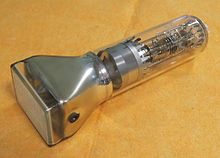
Oscillographic CRT is an evacuated glass flask, inside of which there is an electron gun , a deflecting system and a luminescent screen. The electron gun is designed to form a narrow electron beam and focus it on the screen. Electrons are emitted by an indirect cathode with a heater due to the phenomenon of thermionic emission . The intensity of the electron beam and, consequently, the brightness of the spot on the screen is regulated by a voltage negative at the control electrode relative to the cathode. The first anode serves to focus, the second to accelerate electrons. The control electrode and the anode system form a focusing system .
The deflection system consists of two pairs of plates arranged horizontally and vertically. The horizontal plates, called vertical deflection plates , apply the test voltage. To the vertical plates, which are called horizontal deflection plates , a sawtooth voltage is applied from the sweep generator. Under the influence of the generated electric field, flying electrons deviate from their original trajectory in proportion to the applied voltage. A luminous spot on a CRT screen draws the shape of the signal under investigation. Thanks to the sawtooth voltage, the spot moves across the screen from left to right.
If two different signals are applied to the vertical and horizontal deflecting plates, then Lissajous figures can be observed on the screen.
On the CRT screen, one can observe various functional dependences, for example, the current – voltage characteristic of a two-terminal device , if a signal is proportional to the horizontal deviation plates proportional to the changing voltage applied to it, and a signal proportional to the current flowing through it to the plates of vertical deviation.
Oscillographic CRTs use electrostatic beam deflection, because the signals under investigation can have an arbitrary shape and a wide frequency spectrum , and the use of electromagnetic deflection under these conditions is impossible due to the dependence of the impedance of the deflecting coils on the frequency.
In oscillographic CRTs, magnetic focusing of the electron beam is often used, which allows a smaller point size on the screen to be achieved. (See article electron gun ) .
Low-frequency tubes (up to 100 MHz)
The electrostatic deflection system of such tubes consists of two pairs of deflection plates, vertical and horizontal deflection, located inside the CRT.
When observing signals having a frequency spectrum of less than 100 MHz, the time of flight of electrons through the deflecting system can be neglected. The time of flight of electrons is estimated by the formula:
Where and - respectively, the charge and mass of the electron, - the length of the plates, - voltage of the anode.
Beam deflection in the plane of the screen in proportion to the voltage applied to the plates (assuming that during the passage of electrons in the field of the deflecting plates, the voltage on the plates remains constant):
Where - the distance from the center of deflection of the plates to the screen, - the distance between the plates.
To reduce the parasitic inductance of the terminals of the deflecting system, its conclusions are often made not on the tube base, but in the immediate vicinity of the plates.
In CRTs used to observe rarely repeated and single signals, phosphors with a long afterglow time are used.
Tubes above 100 MHz
For rapidly changing sinusoidal waveforms, the deviation sensitivity begins to decrease, and when the sinusoid period approaches the time of flight, the deviation sensitivity decreases to zero. In particular, when observing pulsed signals having a wide spectrum (the period of the upper harmonic is equal to or longer than the flight time), this effect leads to a distortion of the waveform due to the different sensitivity of the deviation to different harmonics. An increase in the anode voltage or a decrease in the length of the plates can reduce the time of flight and reduce these distortions, but the sensitivity to deviation decreases. Therefore, for oscillography of signals whose frequency spectrum exceeds 100 MHz, the deflecting systems are made in the form of a traveling wave line, usually a spiral type. The signal is fed to the beginning of the spiral and the form of an electromagnetic wave moves along the axis of the system with a phase velocity :
Where Is the speed of light, - spiral pitch - the length of the spiral. As a result, the influence of the time of flight can be eliminated by choosing the speed of flight of electrons equal to the phase velocity of the wave in the direction of the system axis.
To reduce signal power loss, the outputs of the deflecting system of such CRTs are made coaxial . The geometry of the coaxial inputs is selected so that their wave impedance corresponds to the wave impedance of the spiral deflecting system.
Post-Acceleration Tubes
To increase the sensitivity to deviation, it is necessary to have a low anode voltage, however, this leads to a decrease in the image brightness due to a decrease in the electron velocity. Therefore, in the oscillographic CRT, an after-acceleration system is used. It is a system of electrodes located between the deflecting system and the screen, in the form of a conductive coating deposited on the inner surface of the CRT housing.
Amplifier tubes
In broadband CRTs operating in the several GHz band, brightness amplifiers are used to increase brightness without loss of sensitivity. The brightness amplifier is a microchannel plate located inside a CRT in front of a fluorescent screen. The plate is made of special semiconducting glass with a high secondary emission coefficient. The electrons of the beam, falling into the channels (whose diameter is much smaller than their length) knock out secondary electrons from its walls. They are accelerated by the field created by the metal coating at the ends of the plate and, falling on the channel walls, knock out new electrons. The total gain of the microchannel amplifier may be 10 5 ... 10 6 . However, due to the accumulation of charges on the channel walls, the microchannel amplifier is effective only for pulses of the nanosecond range, single or following with a low repetition rate.
Scale
To measure the parameters of the signal reproduced on the CRT screen, the count should be made on a scale with divisions. When applying the scale to the outer surface of the CRT screen, the measurement accuracy is reduced due to parallax caused by the thickness of the screen. Therefore, in modern CRTs, the scale is done directly on the inner surface of the screen, that is, it practically coincides with the image of the signal.
Photographic Recording Tubes
To improve the quality of contact photography of the signal, the screen is made in the form of a fiberglass disk. This solution allows you to transfer the image from the inner surface to the outer one while maintaining its sharpness. In this case, the image blurring is limited by the diameter of the glass fiber filaments, which usually does not exceed 20 microns. In CRTs designed for photographic recording, phosphors are used whose emission spectrum is consistent with the spectral sensitivity of the film.
Literature
- Vukolov N.I., Gerbin A.I., Kotovschikov G.S. Reception cathode ray tubes: Reference book .. - M .: Radio and communications, 1993. - 576 p. - ISBN 5-256-00694-0 .
- Zhigarev A.A., Shamaeva G.T. Electron-beam and photoelectronic devices: Textbook for high schools. - M .: Higher school, 1982.- 463 p. , ill.