P-400 - a series of Soviet high-precision radio telescopes for long-range space communications in the DM and SM wave bands. Further development of the high-precision small-series radio telescope TNA-400 . It is a receiving antenna; The transmitting modification of the antenna is called P-400P .
| P-400 | |
|---|---|
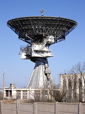 View of the P-400P radio telescope. The second platform. Zaozernoe . | |
| Type of | radio telescope |
| Location | Zaozernoye , Crimea , Russia / Ukraine [1] |
| Coordinates | |
| Wavelengths | radio waves λ = 2; 3.5; four; 5; 6 cm |
| Diameter | 32 m. |
| Mount | azimuthal elevation type |
| Dome | no |
Content
- 1 Design
- 2 Features
- 3 Current status
- 3.1 Antenna P-400P in Yevpatoriya
- 3.1.1 Ukraine
- 3.1.2 Russia
- 3.2 Antenna P-400P in Ussuriysk
- 3.3 P-400 antenna in Irben
- 3.3.1 Scientific tasks
- 3.1 Antenna P-400P in Yevpatoriya
- 4 notes
- 5 Links
Design
The antenna is made according to a two-mirror scheme with a parabolic reflector profile. Each antenna consists of:
- 32-meter mirror;
- counterreflector;
- irradiating system;
- waveguide paths;
- slewing ring;
- electric power drive;
- angle sensors;
- guidance equipment;
- cabins for placement of transceiver equipment.
The design of the mirror includes a support base and a frame made of steel with an accuracy of ± 10 mm, as well as reflective shields made of aluminum alloys mounted on adjusting supports.
The base of the rotary support device is a fixed foundation tower, which is a reinforced concrete building in the form of a hollow truncated twelve-sided pyramid, mounted on a monolithic plate, which ensures the stability of the entire antenna system. Electrical and radio equipment is located inside this tower, as well as in the cabins on the rotating part of the slewing ring in the immediate vicinity of the mirror.
The rotation of the antenna is provided by a turntable with a large base between the bearings of the vertical axis. An azimuth-elevation-type reference rotary device with intersecting mutually perpendicular axes allows you to direct the antenna in the vertical (elevation) plane in the range from - 2 to + 105 ° and in the horizontal (azimuthal) plane ± 330 °.
The mirror system rotates relative to the executive axes using azimuthal and elevation electromechanical drives with smoothly varying angular velocities. Guidance drives are designed to operate at wind speeds of up to 25 m / s. Electric drives are controlled by a 2-channel circuit; Each kinematic drive circuit has its own control channel.
The antenna pointing system can operate in the following modes:
- semi-automatic angle control;
- semi-automatic speed control;
- program management.
Electrical equipment operates from a three-phase alternating current network with a voltage of 380 V and a frequency of 50 Hz.
The P-400P antenna uses a coaxial waveguide irradiator, the central waveguide of which is a centimeter-wave emitter, and the outer tube is a decimeter one. The P-400 antenna uses a hyperbolic counterreflector with a diameter of 4.5 m (~ 15λ), and the P-400P antenna uses a flat counterreflector of small electrical dimensions (5 ... 6 λ) placed in the near field of the irradiator at a distance commensurate with the wavelength, which allows, while maintaining the effective use of the surface of the mirror, to significantly reduce the deformation of the mirror system.
Energy canalization from the input of the irradiator to the receiving devices in both antennas is carried out by the coaxial path in the decimeter range and the waveguide in the centimeter range. Before transmitting devices, energy is channelized by waveguides in the centimeter and decimeter ranges [2] .
Features
The P-400 antenna provides simultaneous reception and transmission in the ranges λ = 2; 3.5; four; 5; 6 cm, and the P-400P antenna - in the ranges λ = 5; 6; 32; 39 cm. At λ = 2 cm, operation is possible at satisfactory values of the effective area and noise temperature [2] .
After adjusting the position of the mirror reflective shields, the root-mean-square accuracy of the formation of the reflective surface (RMS) of 0.5 mm was obtained. From the influence of gravitational and wind loads, the standard deviation increases to 1.3 mm, which makes it possible to use the antenna on radio waves up to 2 cm.
The irradiating system of the P-400 antenna contains a pyramidal horn of large electric length and pathogens DM and SM ranges. In the SM range, the out-of-phase field in the aperture exceeds 2π, as a result of which the width of the pattern is constant over a wide frequency range. This allows you to provide work from λ = 30 cm to λ = 2 cm when changing the pathogen SM range.
The P-400P antenna in Yevpatoriya is one of the most powerful long-range space communications transmitters in Europe [3] .
Current status
P-400P Antenna in Yevpatoriya
Ukraine
The creation of a pulsed radar based on the radio engineering systems of the National Space Control and Test Center ( ADU-1000 (receiving antenna) and P-400 (radiating antenna) of Ukraine for forecasting asteroid hazards, cataloging space debris , exploring the solar corona, near solar and interplanetary plasma, as well as for radio astronomy research of deep space.
It is shown that when using large-sized antennas ADU-1000 and P-400, such a radar at a wavelength of about 30 cm at altitudes of about 100 km detects objects with a minimum size of about 0.7 cm.
With the appropriate retrofitting of the ADU-1000 radiometer with rangefinder equipment, the use of the ADU-1000 - P-400 radio line allows you to create three-dimensional images of the spatial profile of the plasma density in the near-solar space and its temporary changes, which will help to reveal the mechanisms of phenomena occurring in the near-solar plasma [3] .
Due to lack of funding and interest, the project was not implemented. In November 2013, the nearby ADU-1000 antenna was demolished.
Russia
Roscosmos plans to restore the operation of the transmitting antenna in interplanetary missions [4] , but after the issue of the demolition of hotels built in previous years in an insecure zone directly around the antenna is decided.
P-400P Antenna in Ussuriysk
- installed on the basis of the Eastern Center for Long-Range Space Communications , it is planned to restore the antenna and prepare for control of the Phobos-Soil spacecraft, to finalize the antenna for work on new radio frequency bands. Installing an X-band transmitter with a power of at least 10 kW. The P-400 antenna system will be used as a backup if the RT-70 cannot be used.
P-400 Antenna in Irben
- installed on the basis of the former Space Intelligence Station, now Ventspils International Radio Astronomy Center . The Russian authorities were considering the option of destroying the antenna after the withdrawal of troops from the territory [5] .. In 2014-2015, the receiving antenna underwent a deep modernization [6] [7] [8] . The antenna was disassembled to the base, all drives were replaced, the control system. The antenna mirror, weighing almost 60 tons, was lowered to the ground and the metal frame was reconstructed, the reflective plates were shifted [5] . The original specification was retained, so now the telescope has a very high angular velocity for an astronomical instrument [5] . Modernization was more profitable than the construction of a new similar antenna [5] .
In 1995, the telescope equipment was destroyed [5] . Until 2004, only the Academy of Sciences of Latvia allocated the minimum funds for restoration. Then the telescope was transferred to Ventspils University College and the mayor of Ventspils lobbied for funding [5] . Since 2009, all mechanics — motors, drives, control systems [5] - have been updated with European infrastructure grant funds. The antenna is equipped with new receivers at wavelengths of 18, 6 and 5 centimeters, registration systems. Since 2016, astronomical observations have been conducted almost daily [5] . The main task is connected with work in the European VLBI network.
Scientific Tasks
Observation of astrophysical objects
- Since 2016, it is part of the European Radio Interferometric Network (EVN). Observations on VLBI programs are conducted at least three times a year, in sessions of three weeks. [5] .
- The priority is the observation of supermassive black holes and jets in the centers of active galaxies [5] .
- Solar polarimetric studies [5] .
- Coronal magnetic field on the Sun [5] .
- Space debris location, until 2014, together with RT-70 in Yevpatoriya [5] .
- Since December 2015, work with Radioastron . For 2017, the 32-meter antenna in Irben is one of the most active terrestrial “shoulders” of Radioastron. [5] .
Notes
- ↑ This settlement is located on the territory of the Crimean peninsula , most of which is the subject of territorial disagreements between Russia , which controls the disputed territory, and Ukraine , within the borders of which the disputed territory is recognized by the international community. According to the federal structure of Russia , the subjects of the Russian Federation are located in the disputed territory of Crimea - the Republic of Crimea and the city of federal significance Sevastopol . According to the administrative division of Ukraine , the regions of Ukraine are located in the disputed territory of Crimea - the Autonomous Republic of Crimea and the city with special status Sevastopol .
- ↑ 1 2 Chapter 8. Terrestrial antenna systems //: collection / Ed. A. S. Vinnitsky. M.: Radio and communications, 1993. S. 139-175.
- ↑ 1 2 Newsletter of the Kharkiv National University imeni V.N. Karazina. Radiophysics and Electronics, No. 834. 2008. p. 25-30 \\ A.F. Sorokin, A.A. Sorokin, M.M. Gorobets, O.V. Sokolova Radiolocation complex for post-atmospheric conditions
- ↑ Roscosmos Agency shared its plans for Crimea
- ↑ 1 2 3 4 5 6 7 8 9 10 11 12 13 14 Latvian secret aerial of the times of the USSR will serve astronomy
- ↑ Dismantling the antenna at the end of 2014
- ↑ Photo: The antenna of the Irbensky radio telescope was installed using a huge crane . lsm.lv (June 10, 2015). Date of treatment December 8, 2016.
- ↑ ltvpanorama. Irbenē pēta Visuma melnos caurumus (Latvian) . YouTube (January 3, 2016). Date of treatment December 9, 2016.
Links
- Chapter 8. Terrestrial antenna systems //: collection / Ed. A. S. Vinnitsky. M.: Radio and communications, 1993. S. 139-175.
- Bulletin of KNU
- Don P. Mitchel. Soviet Telemetry Systems. Deep space communication centers
- The current state of the P-400P (2nd site of NTsUIKS) on Youtube