"Vanguard" ( Eng. Vanguard - " Vanguard ") - British battleship of the period of the Second World War . Designed in 1939 - 1941, taking into account the alleged delays in commissioning battleships of the Lyon type, as a more urgent project, during the construction of which it was possible to use the backlog of 381-mm gun installations stored in warehouses from the 1920s . Despite the hasty construction, the battleship laid down in 1941 was not put into operation before the end of the war, and after the war its completion slowed down even more and was adopted only in 1946 , becoming the last battleship to enter service in history, as well as the largest from British battleships. The post-war history of the ship, as well as other battleships that survived the war, turned out to be relatively short. In the first post-war years, “Vengard” was repeatedly used as a royal yacht , making trips to South Africa and the Mediterranean. In addition, for some time the battleship was already used as a training battalion, and in some periods it served as the flagship of the Navy of the metropolis . Since 1954, the ship was put into reserve and remained in it until it was withdrawn from service and sold for scrap in 1960 .
| Wangard | |
|---|---|
| Hms vanguard | |
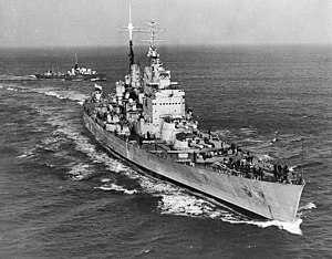 Wangard in 1950 | |
| Project | |
| Preceding type | type " King George V " type " Lyon " |
| Service | |
| Class and type of vessel | Battleship |
| Organization | UK Navy |
| Manufacturer | John Brown and Company , Clydebank |
| Ordered to build | March 14, 1941 |
| Construction started | October 2, 1941 |
| Launched | November 30, 1944 |
| Commissioned | August 9, 1946 |
| Withdrawn from the fleet | June 7, 1960 |
| Status | Scrapped in 1960 |
| Main characteristics | |
| Displacement | 46 102 dl. t standard 51 420 dl. t full |
| Length | 248.3 m |
| Width | 32.9 m |
| Draft | 10.4 m |
| Reservation | citadel belt: 343–356 mm traverses: 305 mm deck of the citadel: 125-150 + 37 the tip of the belt: 51-64 mm tip deck: 64-125 mm GK towers: 150—343 mm barbette towers GK: 305-325 mm conning tower: 25–75 mm |
| Engines | 8 triple water tube boilers of the Admiralty type 4 MH Parsons |
| Power | 130,000 liters from. estimated up to 135 560 liters from. on trials |
| Mover | 4 screws |
| Speed | 29.5 knots up to 31.57 knots in trials |
| Sailing range | 8,400 miles at 14 knots 5350 miles at 25 knots |
| Crew | 1995 people, including 115 officers |
| Armament | |
| Artillery | 4 × 2 - 381 mm / 42 Mk.IA |
| Flak | 8 × 2 - 133 mm / 50 Mk.I 10 × 6 - 40 mm Bofors 1 × 2 - 40 mm Bofors 11 × 1 40 mm Bofors |
Content
- 1 Development History
- 2 Design
- 2.1 Enclosure
- 2.2 Booking
- 2.3 Structural underwater protection
- 2.4 Power installation
- 2.5 Electrical equipment and auxiliary mechanisms
- 2.6 Armament
- 2.6.1 Main Caliber
- 2.6.2 Medium caliber
- 2.6.3 Anti-aircraft artillery
- 2.6.4 Aircraft armament
- 2.6.5 Fire control systems
- 2.6.6 Radar and electronic equipment
- 3 Service History
- 4 Project Evaluation
- 5 notes
- 6 References and sources
- 7 Literature
Development History
As of 1939, the construction dates for new battleships of the Lyon type were constantly disrupted. This situation was mainly due to the long development and completion of the new 406 mm guns, which in 1939 existed only on paper. The introduction of 356 mm King George type battleship towers was accompanied by constant problems and was close to critical. In addition, the power of these guns did not satisfy the British admirals. The assessment of the estimated balance of power at sea, set out in the memorandum of March 3, 1939, was also pessimistic. The neutralization of the Italian fleet at the Mediterranean Theater was entrusted to France. It was assumed that by the end of 1943 the German Scharchnorst , Gneisenau and 5 subsequent battleships would be opposed by two Lyons, five King George , Hood , Ripals and Rinaun . English intelligence did not have reliable data on the construction of Japanese battleships of the Yamato type, but the British suggested that in addition to the 10 old battleships, the Japanese would commission four new battleships with 406 mm guns and two battlecruisers with 320 mm guns. The British at this theater could oppose them with only two Lyons, two Nelsons, five upgraded battleships of the Queen Elizabeth type and three slow-moving battleships of the Rivenge type. Line cruisers were supposed to be kept at the European theater, so there was an acute shortage of high-speed heavy ships [1] [2] .
| Estimated balance of power at the end of 1943 [1] | |||
|---|---|---|---|
| Britain in Europe | Germany | ||
| 1939 program battleships [approx. one] | 2 | new battleships [approx. 2] | 5 |
| King George | 5 | Scharnhorst | 2 |
| battle cruisers [approx. 3] | 3 | Deutschland | 3 |
| TOTAL | 10 | TOTAL | 7 + 3 |
| Britain in the Far East | Japan | ||
| Lion | 2 | new battleships [approx. four] | four |
| Nelson | 2 | Nagato | 2 |
| Worthspite [approx. 5] | 3 | Fuso | 2 |
| Barham [approx. 6] | 2 | " Ise " | 2 |
| Royal Sovereign | 3 | Congo | four |
| new battlecruisers | 2 | ||
| TOTAL | 12 | TOTAL | 16 |
In the circumstances, the British remembered the four 381-mm towers of the Mk I , which remained after the conversion of the Koreiges type cruisers to aircraft carriers . As part of a cheap palliative solution, it was proposed to use these towers for the construction of a high-speed, well-protected battleship with a displacement of 40,000 dl. t and a speed of 30 knots. After modernization, the estimated operating time of the towers was to be at least 25 years. The main task of the new ship was to become the hunt for the alleged 320 mm linear and numerous 203 mm heavy Japanese cruisers . And if the presence of the former was hypothetical, the latter represented a real threat, since the British cruisers clearly lost to them in all respects. It was essentially a revived concept of a battlecruiser, a kind of “neo- Hood ”. According to the plan, if necessary, he had to stand in line and withstand 406-mm battleships. If the resulting hybrid were successful, it would be possible to build ships of the same type using the 381 mm Rivenge-type battleship towers [1] [2] that were freed up when the fleet was withdrawn from the fleet.
The proposal has been reviewed and approved by the Naval Headquarters. The Department of Naval Engineering was tasked with developing a preliminary design of a battleship with a displacement of 40,000 tons , a speed of 30 knots and eight 381-mm guns. Three preliminary projects were formed. Project “15A” had a displacement of about 38,000 tons. Project “15C” from project “15B” differed only in that it was proposed to use a power plant designed for the “Lyon”. Drawings for it have already been developed and this significantly reduced the development time. The development department itself recommended the "15V" option, but the "15C" decided to build, hoping to reduce the construction time. The department of naval engineering was given the task of starting the development of working drawings [1] [2] .
Development was interrupted by the outbreak of World War II. September 11, 1939 all work on the project was suspended. They returned to the project when in December 1939 Winston Churchill became interested in him. He liked the opportunity in a short time to get a battleship, the lack of which was constantly felt by the fleet. In February 1940, by order of Churchill, work was resumed. On February 27, 1940, at a meeting of the Admiralty , clarifications were made to the terms of reference. In particular, there was a demand to establish a thin belt at the extremities, increase the thickness of the reservation of turret mid-caliber compartments, and equip an armored auxiliary steering post in the stern. The armament included four UP anti-aircraft missile launchers. The plants were heavy and later recognized as ineffective. The only advantage of including them in the project was the displacement stock that appeared after their dismantling [3] [2] .
Based on these requirements, 41,200-ton 15D project was developed. It was approved on May 20, 1940. Numerous changes were made to the project related to the experience gained in operating King George type battleships. The delay in design was also facilitated by the suspension of work from June to October 1940 due to the high workload of the bureau. The changes resulted in the final project “15E”, which was adopted by the Admiralty Council on April 17, 1941 [3] [4] .
An order for construction was issued on March 14, 1941 to John Brown and Co. A full set of drawings arrived at the shipyard 10 days later and on October 2 the official laying of the battleship took place. On November 3, the new ship received the name "Vengard" [3] . The attack on Pearl Harbor and the death of the Prince of Wales and Ripals made building a new battleship a matter of first priority. The Admiralty hoped to put it into operation before the end of 1944. The number of employees at its construction was brought up to 3.5 thousand, however, even after the suspension of work on the Bellerophon cruiser under construction and the John Brown merchant ships, there were not enough qualified personnel. The work was noticeably behind the original schedule. In mid-1942, even the idea arose to remake a semi-finished battleship into an aircraft carrier. However, realizing the low combat effectiveness of such a converted aircraft carrier, this idea was abandoned [5] [4] .
During the construction process, the experience of the death of the Prince of Wales battleship was taken into account and after its analysis they improved anti-torpedo protection , and the number of anti-aircraft guns was increased to 76 40 mm and 12 20 mm. The standard displacement became the same as that of the Khuda, reaching 42,300 tons, and the fuel supply increased to 4,850 tons. On November 30, 1944, the Wengard was launched. The baptism ceremony was held by Princess Elizabeth . Completion afloat before the end of World War II did not have time to complete. After the war, the pace of work slowed down and the battleship entered the acceptance tests only in April 1946 [5] [4] . The total cost of construction amounted to 11 530 503 pounds. Arms without taking into account the initial cost of buying towers of the main caliber cost the British treasury 3 3,868 pounds [6] .
| Project data of the battleship Wangard [4] | |||||||
|---|---|---|---|---|---|---|---|
| Project | 15A | 15V | 15C | 15D | 15E | Wangard September 1942 | Wangard 1946 |
| Maximum length, m | 236.4 | 245.5 | 245.5 | 246.7 | 246.7 | 247.8 [5] | 248.2 [6] |
| Width m | 31.7 | 32 | 32 | 32,2 | 32.9 | 32.9 | 32.9 |
| Draft is average, m | 8.8 | 9.1 | 9.1 | 9 | 8.9 | 9.09 | 9.38 |
| Maximum power, l. from. | 110,000 | 143,000 | 130,000 | 130,000 | 130,000 | 130,000 | 130,000 |
| Maximum speed, knots | 29.2 | 31 | thirty | 30.25 | 30.25 | thirty | |
| Fuel reserve, dl. t | 3800 | 3800 | 3800 | 3800 | 4100 | 4850 | 4950 |
| Distribution of weights, dl. t | |||||||
| Body | 14 300 | 15 500 | 15 500 | 15 600 | 16 100 | 16 500 | 18 657 |
| Reservation | 14,000 | 14,450 | 14 300 | 15 500 | 15,200 | 15 350 | 14 741 |
| Power plant | 2750 | 3450 | 3200 | 3250 | 3250 | 3150 | 3251 |
| Armament | 5900 | 5900 | 5900 | 5750 | 5950 | 6100 | 6718 |
| Equipment | 1100 | 1100 | 1100 | 1100 | 1100 | 1200 | 1247 |
| Standard displacement | 38,050 | 40 400 | 40,000 | 41,200 | 41,600 | 42,300 [7] | 44,614 [7] |
Design
Corps
Initially, the shape of the Wangard hull was not much different from the shape of the King George hull. Due to the requirement to provide the possibility of firing the main caliber at a zero elevation angle directly on the nose , the deck of the latter did not have a nose lift. Because of this, the deck was constantly flooded and the “Kings” were considered “wet” ships [4] . However, in practice, such firing led to destruction of the deck, which made it impossible. Therefore, such a requirement was abandoned and the new battleship received an inclined stem and a significant rise in the deck of the nose. While the freeboard height in the middle of the ship was 6.9 m almost the same as that of King George, it was 11.2 m in the stem, versus 8.45 m. It was larger in the stern as well - 7.8 m against 7.2 m. “Vengard” had three breakwaters - one in the middle of the forecastle and two in front of the bow towers of the main caliber. Thanks to all this, he did not bury his extremities in the water on a wave, was “dry” even in bad weather and had good seaworthiness up to a full speed of 30 knots. According to this indicator, it was considered the best battleship in Britain, and even the world [8] .
| Comparative freeboard height of British battleships, m [9] | ||||||
|---|---|---|---|---|---|---|
| ship | King George V | Lion | Project 15D | Project 15E | Wangard 1942 | Wangard 1946 |
| nose | 8.46 | 8.53 | 9.91 | 9.91 | 11.18 | 11.28 |
| center | 6.93 | 6.86 | 6.86 | 7.01 | 6.91 | 7.01 |
| stern | 7.24 | 7.47 | 7.47 | 7.62 | 7.52 | 7.77 |
Wangard was considered a fairly stable weapon platform - the pitching period was 14.3 seconds, about the same as that of King George. Because of the long hull, maneuverability was not perfect, but it did not cause any particular complaints. The ship listened well to the helm and at full speed with a maximum rudder shifting to the side of 35 ° had a tactical circulation diameter of 1000 m. The maximum roll was 7.5 °. At full speed, after feeding “full back”, the time for a complete stop was 4.75 minutes. The only unpleasant moment was vibration when the rudder was completely shifted at speeds of about 20 knots, which is why it was not recommended [8] .
| Stability Parameters [7] | when tilted in June 1946 | in the presence of holes above the armored deck (1946) | ||||
|---|---|---|---|---|---|---|
| standard displacement | lightweight ship | combat displacement | complete displacement | lightweight ship | complete displacement | |
| displacement, dl. t | 44,500 | 45 116 | 50 145 | 51 420 | 45 116 | 51 420 |
| metric | 45,212 | 45 838 | 50 947 | 52,243 | 45 838 | 52,243 |
| metacentric height , m | 1.76 | 1.80 | 2.28 | 2,50 | 1.10 | 1.89 |
| angle of maximum restoring moment, ° | 35 | 35 | 34,4 | 35 | fourteen | 10 |
| angle of loss of stability, ° | 60.5 | 60.7 | 65.3 | 68 | 25 | eighteen |
Compared to previous types, the compartmentalization has been improved. The number of watertight compartments was brought to 27. At the same time, for the first time, watertight bulkheads were brought to the main deck and at the extremities. All these compartments had watertight vertical shafts. The total number of watertight rooms below the main deck was 1,059. Ten bulkheads above the middle deck were also watertight to prevent the rapid spread of water [8] .
From the point of view of organizing the struggle for survivability, the entire ship was divided into 6 sections with its own division for the struggle for survivability and its leader. Each section had its own post of energy and vitality. In addition to them, there were also main and auxiliary posts. The division into sections allowed faster, on the spot, the division head to make decisions on an emergency in case of communication disruptions. But it required greater coordination of the work of people working in neighboring sections [8] .
We tried to improve living conditions. The battleship was designed for action in any latitude. For operation in northern latitudes, steam heating was used for most posts and weapon systems. For service in the tropics, there was an air conditioning system in the compartments below the armored deck and above it in all rooms with “thin” equipment — rooms for radar operators, computer centers for artillery control systems , an aviation control center, radio stations , etc. Under the surface, which were in contact with external environment, asbestos linings were placed for thermal insulation [10] .
Despite the efforts made, the living conditions were not ideal. According to the initial draft, when using the ship as the flagship, the crew was to consist of 76 officers and 1,412 foremen and sailors. The constant increase in anti-aircraft weapons , detection and control systems led to the overflow of a number of premises during combat alert. This was especially true for facilities such as the combat information center. In order to avoid crowding of the crew in working and sleeping premises, the shipbuilding department issued a special memorandum according to which the crew should not exceed 1975 people, including 115 officers [10] .
Booking
The reservation scheme for the Wangard Citadel was almost the same as King George and Lyon. On the one hand, there was simply no time to develop another scheme and it would require additional costs. On the other hand, it was never tested in real combat, so the British simply had no reason to believe that it was not effective. The main belt was 140 m long and was made of cemented armor . Due to the inability to make armor plates 7.3 m high, it was made of three horizontal rows of plates. The rows of plates were shifted relative to each other - the middle one was shifted by half a plate relative to the upper and lower. The first two rows were of constant thickness, the bottom row went in a wedge, decreasing towards the bottom edge. The plates were attached to the casing with armor bolts , and in the area of the joints they were joined together with the help of dowels . The thickness of the main belt was reduced by 1 inch (25.4 mm) compared to King George - in the cellar area it had a thickness of 356 mm (instead of 381 mm) and 343 mm in the central part (instead of 356 mm). In the lower part along the entire length, it was chamfered to 114 mm. Beyond the end towers in the bow and stern, the main belt continued for about 12 m with a transitional belt. He protected the cellar from hitting sharp course corners. The thickness of this belt gradually decreased from 343 mm to 305-260 mm. The main beam of the traverse was 305 mm thick. Under the most unfavorable meeting conditions, the belt protected against 381-mm shells of the cellar at a distance of 75-80 cab and a machine for 85-90 cab [10] .
According to the experience of military operations, unprotected extremities were easily destroyed even by shells of destroyers and cruisers and by fragments of large-caliber shells and bombs, which led to extensive flooding. The presence of transverse watertight bulkheads did not help much, since they too could be broken. Therefore, at Vengard they moved away from the “ all or nothing ” scheme and the extremities received armor protection. The main belt at the extremities continued with a belt of Germanic armor 51-64 mm thick. At the nasal tip, it had a height of 2.45 m and ended at 3.5 m from the stem. In the stern it was higher - 3.4 m and covered the steering compartments. Due to the shape of the case, it had a significant slope of the top edge out. Additionally, 25 mm longitudinal bulkheads were installed. The belt was considered "anti-fragmentation" and its main purpose was to protect against fragments and localize damage from shells of cruisers and destroyers. At favorable angles between the projectile and the armor, it was supposed to protect against medium-caliber armor-piercing shells and provided good protection against the most commonly used high-explosive shells [11] .
| Maximum penetration range of 64 mm armor when hit by a projectile normal [12] | ||
|---|---|---|
| Caliber mm | projectile weight, kg | range, m |
| 152 | 50.8 | 16 500 |
| 150 [approx. 7] | 45.5 [13] | 18 300 |
| 133 | 37,2 | 11 900 |
| 120 | 28.1 | 10 500 |
| 120 | 22.7 | 5900 |
| 114 | 24.9 | 9600 |
The main armored deck went along the upper edge of the main belt, over the cellars had a thickness of 152 mm and 127 mm over the rest of the citadel. An additional layer of 37 mm was laid over the cellars, giving a total protection thickness of 7.5 inches (190 mm). In the nose, the armored deck continued 125 mm thick from the bow traverse to the end of the 280 mm armor. Further along the entire length of the “anti-fragmentation” belt, it had a thickness of 64 mm, ending at 3.5 m from the stem. In this deck, they tried to make as few cutouts as possible and the largest of them was the anchor shaft. In the aft end, the armored deck was thicker - 114 mm, as it covered shafting and steering drives. It was closed by a traverse 100 mm thick installed on the rear wall of the steering compartment [14] .
At the Prince of Wales, in a battle with Bismarck, a shell pierced the side, light bulkheads of anti - torpedo protection (PTZ) and stuck in a 44-mm anti-torpedo bulkhead. Fortunately for the British, he did not burst. But, realizing the possible consequences of such a gap, an additional 37 mm longitudinal bulkheads were installed at Vengard in the cellar area [14] .
Traditionally for the British battleship industry, wanting to save at least a dozen tons of armor, the reservation of barbets was made of variable thickness around the circumference. The thickest were the side walls. The inside, covered with another barbet or superstructures and extremities of the side, had a smaller thickness. Over the main armored deck, the barbets of the 2nd, 3rd and 4th towers in the 30 ° sector on both sides of the diametrical plane had a thickness of 280 mm. At the 4th tower, the inner 280 mm sector closest to the extremities was 33 °. The next sector at 25 ° was 305 mm thick. The side walls had 330 mm. At the bow tower No. 1, the front sector had a thickness of 305 mm and only 20 ° to each side of the diametrical plane. But the internal sectors of 280 mm and 305 mm armor were wider - 45 ° on board [14] [15] .
Despite the tragic consequences of a shell falling into the Prince of Wales conning tower in a battle in the Danish Strait , the British did not depart from their concept of booking it at Wengard. Considering that the probability of getting into the conning tower is not great, its thickness was significantly reduced compared to battleships of other countries [14] . The front wall of the cabin was 76 mm thick, the rest of the walls and the roof were 63.5 mm [6] .
The level of anti-fragmentation protection of objects on bridges and superstructures has increased significantly. Most of the posts and controls of the ship received protection from cementless armor with a thickness of 25 to 51 mm [16] .
| Weight components of the reservation project 15E in 1942 [12] | ||
|---|---|---|
| Type of reservation | long tons | metric tons |
| Main belt, including a continuation in the bow and stern outside the citadel | 4666 | 4740,9 |
| Traverses | 516 | 524.3 |
| Barbets | 1500 | 1524.1 |
| Main deck including barb reinforcements | 4153 | 4219.7 |
| Lower deck in the bow | 362 | 367.8 |
| Lower deck aft | 578 | 587.3 |
| Additional bulkheads | 75 | 76,2 |
| Conning tower | 44 | 44.7 |
| Aft conning tower and communication tubes | 57 | 57.9 |
| KDP booking | 31 | 31.5 |
| Fragmentation belt in limbs | 218 | 221.5 |
| Anti-torpedo bulkhead | 1375 | 1397.1 |
| Additional cellar reservations | 626 | 636.0 |
| Chimney booking | 52 | 52.8 |
| Splinter bulkheads at the extremities | 33 | 33.5 |
| Casemates of 133 mm guns | 443 | 450.1 |
| Circular bulkhead reinforcements | 80 | 81.3 |
| Armored grate | 24 | 24.4 |
| Bulletproof booking of bridges | 110 | 111.8 |
| Booking 133 mm towers | 17 | 17.3 |
| Armor Lining | 40 | 40.6 |
| TOTAL | 15,000 | 15,240.8 |
Constructive underwater protection
The defense of King Jordan was based on the results of research under the Job-74 program and was calculated on the confrontation of a dashboard with a charge of 454-kg TNT . Experience has shown that such a design was ineffective. In the Gulf of Thailand, the Prince of Wales actually failed after two aircraft torpedoes with a twice as weak charge were hit. And after six he went to the bottom. The reasons for this failure were the insufficient height of the longitudinal bulkheads, which reached only the level of the lower deck, their erroneous riveted fastening in the upper part to steel hull structures, the possibility of flooding the premises through the top of the PTZ, covered only by a light bulkhead from shipbuilding steel, shallow depth (only 4 m) gas expansion zones. In addition, large empty flooded volumes outside the anti-torpedo bulkhead (PTP) led to the need for counter- flooding of the opposite side PTA compartments, which reduced the efficiency of their work [16] .
Despite the apparent failure of the King George submarine defense structure, it did not undergo significant changes at Wangard. True, a number of measures were taken to eliminate the identified shortcomings. Underwater protection consisted of three layers. The first empty compartment closest to the side served as an expansion chamber and its task was to distribute the explosion pressure over as large an area as possible. The middle compartment acted as an absorption chamber - it was filled with liquid and its task was to quench the shock force of the blast wave and reduce the velocity of the shell fragments. The inner compartment was empty in order to exclude a hydraulic shock from the middle compartment to subsequent layers of the PTZ. The internal border of this compartment was an armored anti-torpedo bulkhead (PTP) with a thickness of 37 to 44 mm. Between it and the internal compartments there was still a small filter compartment, the task of which was to keep the leaks passing through the PTP. The depth of the PTZ compared to King George was increased, but still did not exceed 4.75 m at the widest point. In the end towers, it decreased to 2.6-3 m. It was also insufficient in the area of the bow boiler houses departments [16] .
The upper part of the PTZ was strengthened, and the height of all anti-torpedo bulkheads was increased by one inter-deck distance and now reached the level of the middle deck. Это увеличивало объём камеры расширения и снижало вероятность разрушения верхней части ПТЗ. Озаботились водонепроницаемостью отсеков расположенных за броней в районе ватерлинии. На «Принс оф Уэлс» в этом месте находились душевые, через негерметичные стенки и потолок которых распространялось затопление. Душевые перенесли на палубу выше — теперь они находились на средней палубе [16] .
| Характеристики противоторпедной защиты по длине корабля [12] | ||||
|---|---|---|---|---|
| Шпангоут | A place | Глубина ПТЗ | Толщина ПТП, мм | Стойкость ПТЗ кг ТНТ расчётная |
| 74 | Передняя часть погреба первой башни | 2,62 | 44,45 | 213 |
| 92 | Между погребами первой и второй башен | 3,58 | 44,45 | 395 |
| 110 | Задняя часть погреба второй башни | 4,14 | 44,45 | 544 |
| 134 | Начало носового котельного отделения | 4.09 | 38,1 | 445 |
| 156 | Между носовыми машинным и котельным отделениями | 4,29 | 38,1 | 499 |
| 178 | Начало кормовых котельных отделений | 4,57 | 38,1 | 590 |
| 200 | Между кормовыми котельными и машинными отделениями | 4,29 | 38,1 | 499 |
| 222 | Конец кормового машинного отделения | 4,32 | 38,1 | 590 |
| 236 | Конец погребов кормовых 133-мм орудий | 3,96 | 44,45 | 490 |
| 247 | Передняя часть погреба четвёртой башни | 3,61 | 44,45 | 408 |
| 283 | Задняя часть погреба четвёртой башни | 2,97 | 44,45 | 272 |
Энергетическая установка
Конструкция силовой установки была весьма консервативной, так как была взята от проекта «Лайона», а для того, в свою очередь, позаимствована у «Кинг Джорджа». Поэтому параметры пара — давление 28 атм, температура 370°С, были низкими не только по меркам 1940-х, но и для 1930-х годов. Техническая отсталость британской промышленности не позволила создать для турбо-зубчатого агрегата двухступенчатый редуктор . Поэтому был применен одноступенчатый с передаточным числом 1:10 [17] [18] .
Для большей живучести четырёхвинтовая силовая установка была разбита на 4 блока с индивидуальным приводом на винт. В каждый блок входили котельное отделение на два котла, турбинное отделение и отсек вспомогательных механизмов. Каждый блок оснащался индивидуальной системой подачи топлива, воды и масла. Также для увеличения живучести котельные и турбинные отделения обоих бортов чередовались в шахматном порядке. При этом валы внешних винтов получились значительно длиннее внутренних [18] .
Главной проблемой была необходимость увеличения потребной мощности силовой установки в связи с ростом водоизмещения. Конструкторы решили эту задачу наиболее простым способом — форсировкой турбин. Если по первоначальному проекту мощность одного блока должна была быть 30 000 л. from. при 245 об/мин на валах, то в конце 1942 года был принят форсированный режим с мощностью блока в 32 500 л. from. при 250 об/мин. Это давало суммарную мощность в 130 000 л. from. и обеспечивало 30 узлов при стандартном водоизмещении в 42 300 т и 28,5-29 узлов при полном в 48 500-49 100 т. Хотя проектное водоизмещение было превышено на 2000 т, на испытаниях «Вэнгард» развил 31,57 узла при 256,7 об/мин, мощности на валах 135 650 л. from. и водоизмещении 45 720 т. Благодаря удачным обводам корпуса в июле 1946 года на мерной у Эррана он показал скорость 30,38 узла при водоизмещении 51 070 т. Мощность составила 132 950 л. from. при 250,6 об/мин. Так как британцы на испытаниях не занимались чрезвычайной форсировкой силовой установки, есть основания полагать что «Вэнгард» мог развить скорость и выше 31,5 узла [19] [17] [18] .
Пар вырабатывался восемью трехбарабанными котлами «адмиралтейского» типа. Максимальное рабочее давление в котлах составляло 32 атм , на входе в турбины оно составляло 28 атм [19] [17] [20] .
В каждом машинном отделении находилась одна турбина высокого и одна низкого давления переднего хода с приводом на вал через двойную косузубчатую передачу. Турбина заднего хода была выполнена в одном корпусе с турбиной низкого давления. Первоначально предлагалось установить крейсерские турбины с подсоединением через зубчатый редуктор, но в конце 1942 года от них отказались, желая сэкономить дополнительные 100 т веса. Тем не менее он вырос за счёт других агрегатов и в итоге вес силовой установки остался на проектном уровне в 3250 дл. т [19] [20] .
Все четыре винта были трехлопастными диаметром 4,5 м и изготавливались из марганцевой бронзы . На «Принс оф Уэлс» зоны вращения винтов перекрывались примерно на 0,5 м, что привело к выводу из строя двух валов в результате одного торпедного попадания. Поэтому на «Вэнгарде» расстояние между осями внутренних и внешних валов увеличили с 10,2 до 15,7 м [19] [20] .
Неприятной особенностью силовой установки являлось появление вибрации на высоких оборотах, особенно сильной при 200 об/мин соответствовавшей скорости в 24 узла. Одним из решений этой проблемы было использование разного режима работы внешних и внутренних валов. Та же скорость при меньшей вибрации достигалась при вращении внутренних валов со скоростью 222 об/мин, а внешних 174 об/мин. Также приняли решение заменить внутренние винты на пятилопастные. Но все эти меры окончательно проблему не решили и на скорости в 24 узла было введено ограничение на перекладку руля не более чем на 10° [21] [20] .
Исходя из опыта эксплуатации «Кинг Джорджей», увеличили высоту просвета в турбинных и котельных отделениях и поставили более мощную вентиляцию. По результатам анализа гибели «Принс оф Уэлс» уделили более тщательное внимание конструкции агрегатов и её ударостойкости. Предусмотрели дополнительное охлаждение пара и устранения конденсата . Улучшили конструкцию передней части топок и форсунок . Повысили ударостойкость футеровки топок, которая на «Кинг Джорджах» была склонна к растрескиванию при ударах. Для смягчения последствий взрыва были использованы предохранительные устройства. Благодаря изоляции турбинных отделений и герметизации турбин они могли работать при частично и даже полностью затопленных турбинных отделениях. Главные вентили паропроводов получили помимо ручного дистанционный гидравлический привод с управлением из центрального поста или специального поста управления машинной установкой. В отличие от типа «Кинг Джордж» это позволяло управлять машинной установкой при полном затоплении турбинного отделения. Также предусматривался независимый «перекрестный» паропровод между четырьмя блоками машин, что позволяло подавать пар на турбины блока, в котором вышли из строя котлы. Невозможность такого переключения была одной из причин быстрой потери хода линкором «Принс оф Уэлс». Ещё одной причиной быстрого затопления последнего был развороченный сорванным валом валопровод . В этом отношении мало что можно было сделать. Всё что могли сделать кроме разнесения линий валов, это улучшить герметизацию сальников валопроводов [20] .
Ещё одной не решенной проблемой была дальность плавания. Из-за одноступенчатого редуктора КПД турбин на крейсерских ходах было низким и силовая установка получилась оптимизированной для режима полного хода. Были приняты меры по снижению часового расхода топлива с 363 до 290 г/л. from. в час. Запас топлива вместо 4100 т по проекту увеличили до 4425 т нефти и 427 т дизельного топлива. Это было сделано за счёт расширения бортовых цистерн в средней части корпуса на 0,7 м использованию отсеков двойного дна под концевыми башнями главного калибра. Последние нужно было расходовать в первую очередь из-за взрывоопасности при подводных взрывах. Несмотря на принятые меры, заложенное в 1941 году требование по дальности в 14 000 миль на 10 узлах выполнить не удалось. При чистом днище на наиболее экономичном ходу в 14 узлов дальность составила порядка 8400 миль. В умеренных широтах после 6 месячной службы в результате обрастания днища ход падал до 13 узлов, а дальность до 7400 миль. В тропиках падение было ещё больше — до 11,5 узлов и 6100 миль соответственно. Несколько лучше «Вэнгард» смотрелся на высоких скоростях хода. При чистом днище дальность на 20 узлах составила 6950 миль, на 25 узлах — 5350 миль, 3380 на 28 и 3600 на 29,5 узлах. После полугода службы для полного хода эти цифры падали на 8 % в северных водах и 19 % в тропиках, для умеренных ходов падение было больше — на 17 % и 35 % соответственно [21] [20] .
| Дальность плавания, миль [21] | |||
|---|---|---|---|
| Скорость, узлы | При чистом днище | Через 6 месяцев службы | |
| в умеренных широтах | в тропиках | ||
| Экономичный ход [прим. 8] | 8414 | 7413 | 6100 |
| fifteen | 8250 | 7150 | 5700 |
| twenty | 6950 | 5800 | 4500 |
| 25 | 5350 | 4400 | 3350 |
| 29.5 | 3600 | 3350 | 2900 |
Электрооборудование и вспомогательные механизмы
По первоначальному проекту на «Вэнгарде» предусматривалась установка 6 турбогенераторов и 2 дизель-генераторов вырабатывающих постоянный ток напряжением 222 В. Все они объединялись в кольцевую магистраль. Опыт войны, особенно потеря электропитания крейсера « Белфаст » после подрыва на донной мине, заставил пересмотреть состав и компоновку оборудования. При спуске на воду на «Вэнгарде» стояли 4 турбогенератора мощностью по 480 кВт и 4 дизель-генератора по 450 кВт. Генераторы размещались в 8 отдельных помещениях. Два турбогенератора находились в отсеках по бокам от носовых котельных отделений. Ещё два, предназначавшихся для резервного питания на стоянке, стояли в отсеке вспомогательных генераторов между передними турбинными отделениями. Два дизель генератора находилось спереди носового КО, по бокам от погребов 133-мм орудий. Ещё два размещались по бокам от задних турбинных отделений. По всей длине корпуса под броневой палубой находилось 18 щитовых помещений, объединявших генераторы с потребителями тока [21] [22] .
Первоначально резервный запас пресной воды составлял 390 тонн, но потом в 1947 году его решили сначала увеличить до 490 т, а в 1948 году довели до 590 тонн. При вводе в строй линкор нёс один опреснитель производительностью 200 т воды в сутки и три по 100 т. Первый служил для основных нужд корабля, в том числе во время стоянки. Три других были распределены между отдельными помещениями. Один из них был специального типа и через несколько лет после начала службы он был признан непрактичным и заменён на опреснитель производительностью 200 т в сутки [21] [22] .
Для снабжения сжатым воздухом высокого давления использовались 4 компрессора по 95 л. from. Этот воздух использовался для продувки стволов орудий, стартеров дизелей и т. п. Существовала также магистраль низкого давления, обслуживавшаяся двумя компрессорами по 26 л. from. [21] [22]
Механизмы гидропривода башен главного калибра включали 4 насоса с турбоприводом, находившихся в отдельных отсеках. Рабочее давление насосов 80 атм, производительность — до 28 литров в минуту [21] [22] .
Armament
Главный калибр
| Бронепробиваемость орудий британских линкоров [22] | ||||
|---|---|---|---|---|
| дистанция | Расчетная бронепробиваемость вертикальной / горизонтальной крупповской брони, мм | |||
| кбт | m | 381-мм Mk-I «Вэнгард» | 406-мм Mk-I «Нельсон» | 406-мм Mk-II «Лайон» |
| 75 | 13 890 | 353/50 | 366/49 | 449/36 |
| one hundred | 18 520 | 297/79 | 310/72 | 389/82 |
| 125 | 23 150 | 259/109 | 261/99 | 335/112 |
| 150 | 27 780 | 229/145 | 224/130 | 292/143 |
Главный калибр «Вэнгарда» состоял из восьми 42-калиберных 381-мм орудий Mark I в четырёх двухорудийных башнях . С одной стороны, такой выбор стал шагом назад по сравнению с планировавшимися 406-мм установками для «Лайонов» и установленными на американских линкорах. К тому же орудие проигрывало по баллистическим характеристикам 380-381-мм орудиям линкоров европейских стран. Однако на деле бронепробиваемость 381-мм орудий была не столь кардинально хуже, чем у 406-мм орудий «Нельсона», и на всех дистанциях была лучше бронепробиваемости 356-мм орудий «Кинг Джорджа» [22] .
При этом установка по две двухорудийных башни в носу и корме давала наилучшую с точки зрения управления огнём конфигурацию. Запас 381-мм орудий и снарядов к ним также был велик. Сама конструкция орудия и установок была надёжной и отработанной. 381-мм орудие обладало хорошей кучностью огня и, благодаря возможности заряжания при любом угле возвышения и отработанной конструкции установки, обладало хорошей практической скорострельностью. Конструкция башен потребовала внесения ряда изменений. Бронирование башен было явно недостаточным. Лобовая плита имела толщину всего 229 мм, а крыша — 114 мм. Угол возвышения был ограничен и дальность стрельбы не превышала 12 миль (22,5 км). Пламенепроницаемость установки, спроектированной ещё до Ютландского сражения , также не удовлетворяла требованиям 1940-х годов. Стоявшие на башнях 4,6 м дальномеры также требовали замены [23] .
В первую очередь заменили лобовую плиту на 343-мм с более высокими амбразурами, позволявшими придавать орудиям углы возвышения до 30°. Порты орудий получились довольно большими и пришлось закрыть их сверху специальными броневыми крышками. Крышу заменили на 152-мм плиты нецементированной брони. С крыши убрали командирскую башенку, мешавшую стрельбе возвышенной башни поверх крыши пониженной башни. В качестве противовеса возросшему переднему весу башни пол башни усилили с 51 до 76 мм. Боевое отделение и системы подачи оборудовали пламенепроницаемыми экранами. Вместо 4,5-метровых дальномеров поставили 9-метровые. Впервые в британском флоте башни главного калибра (ГК) получили дистанционный силовой привод для горизонтального наведения [5] [23] .
Системы подачи новых башен были модернизированы под новые удлиненные 879-кг бронебойные снаряды . Станины , цапфы и противооткатные устройства усилили для возможности использования усиленных зарядов из 220,4 кг кордита марки SC-300, придававших бронебойному снаряду начальную скорость в 805 м/с. Использование усиленных зарядов приводило к сильному износу ствола и на практике в условиях мирного времени их не использовали. Штатный заряд сообщал снаряду начальную скорость в 785 м/с [24] .
После всех изменений вращающийся вес башни составил 855 длинных т, на 20 т больше, чем по проекту [23] . Дополнительный вес вооружения получился за счёт увеличение веса командно-дальномерного поста (КДП) с 63 до 70 т, более мощных и тяжёлых гидравлических механизмов (с 63 до 70 т), жидкого носителя (с 80 до 91 т) и ещё 20 т дополнительной анти коррозионной смазки [25] .
Скорость горизонтальной наводки составила 2°/сек, вертикальной — 5°/сек. Техническая скорострельность не изменилась и составила 2 выстрела в минуту. Модернизированные башни получили индекс Mk IN, такой же, как башни на модернизированных в 1930-е годы линкорах и линейных крейсерах [23] .
Одной из проблем стала необходимость переделки систем подачи. На момент создания установок перед Первой мировой войной общепринятой практикой было размещение снарядных погребов под зарядными . Считалось, что для взрывоопасных погребов большую опасность представляют мины и торпеды . К началу Второй мировой войны , по результатам Ютланда, осознали опасность попадания снарядов в погреба, после чего зарядный погреб стали размещать в самом низу. Менять старую систему подачи полностью было слишком затратно, поэтому разработчики пошли на компромисс. Зарядный погреб был размещён в самом низу, однако заряды из него подавались в промежуточное перегрузочное отделение, располагавшееся над снарядным погребом. Уже оттуда заряды перемещались в неизмененную систему подачи. Для дополнительной защиты перегрузочное отделение оснащалось пламенепроницаемыми дверями, а заряды в него подавались в специальных пеналах [26] .
При расчёте стандартного водоизмещения боезапас был учтён по норме 80 снарядов на ствол с таким же количеством зарядов к ним. Максимальный боезапас при полном водоизмещении составлял по 114 снарядов и зарядов на ствол [5] .
Средний калибр
Универсальная артиллерия повторяла таковую на линкорах типа «Кинг Джордж V» — шестнадцать 133-мм универсальных орудий Mk I в двухорудийных башнях. Рассматривались варианты вооружения достаточно удачными британскими 114-мм зенитными и американскими 127-мм орудиями. От обоих отказались, так как британским адмиралам нравилась возможность 133-мм 36,5-кг снаряда остановить эсминец или поразить крейсер противника [27] .
Установки, разработанные для «Кинг Джорджей», критиковались за недостаточную поворотливость [28] и скорострельность [29] . «Вэнгард» получил новые, более совершенные установки Mark 1* [25] . Они имели большую скорость наведения — по 20 °/с в вертикальной и горизонтальной плоскостях [30] [31] . Боевое отделение было перепланировано. Установки также получили дистанционный силовой привод RP10* для вертикального и горизонтального наведения [25] . Возросла и скорострельность. По разным данным она составляла от 9 [30] до 18 [32] выстрелов в минуту [прим. 9] . Установки вместе с орудиями, насосами, запасами и штатными расчётами весили 854 т, что на 29 т превысило проектную величину [25] .
Заряжание было раздельно гильзовым. В боекомплект входили два типа снарядов — полубронебойные для надводных целей и фугасные для воздушных. Данных по составу боекомплекта «Вэнгарда» нет, но к концу войны для 133-мм орудий до половины фугасных снарядов имели радиолокационный взрыватель [33] . Оба типа снарядов имели свою линию подачи с подъемниками в виде бесконечной цепи. Для гильз с порохом была отдельная линия подачи такого же вида. Боеприпасы хранились в общем погребе и подавались из него в перегрузочное отделение под башней. Отсюда они подъемниками подавались в боевое отделение. Снаряды для надводных целей подавались горизонтально, а для воздушных целей и заряды — вертикально. Для башен № 2 и № 3 (средние, на один уровень надстройки выше концевых) подача прерывалась на уровне средней палубы в промежуточном перегрузочном отделении. Подача снарядов в промежуточное отделение шла горизонтально ковшевым подъемником. Верхние линии подачи на всех башнях был одинаковыми. В отличие от установок «Кинг Джорджей» с ручным заряжанием, новые установки получили автомат заряжания и автомат выставления временной задержки взрывателя [31] .
Зенитная артиллерия
| Gun | НУРС | 40-мм «Пом-пом» | 40-мм «Бофорс» | 20-мм «Эрликон» | |||||||||
|---|---|---|---|---|---|---|---|---|---|---|---|---|---|
| Installation | UP 178-мм | Mk VIII | Mk IV | ∑ | Mk VI | BUSTER | Mk II STAAG | Mk III | Mk VII | ∑ | Mk XIV | Mk XII | ∑ |
| количество стволов | 8 | four | 6 | 2 | 2 | one | one | 6 | 2 | ||||
| Изменение состава зенитного вооружения | |||||||||||||
| проект 15Е, апрель 1941 | four | 6 | 48 | ||||||||||
| сентябрь 1942 [5] | 9 | one | 76 | 12 | 24 | ||||||||
| июнь 1943 [34] | 9 | one | 56 | 12 | 24 | ||||||||
| начало 1945 [34] | 9 | one | 56 | 6 | fourteen | 64 | |||||||
| апрель 1945 [34] | 9 | one | 7 | four | 67 | 9 | eighteen | ||||||
| 1946 [34] | 10 | one | eleven | 73 | |||||||||
| 1954 [35] [прим. 10] | 10 | one | four | 66 | |||||||||
| 1956 [35] | four | four | |||||||||||
Вплоть до проекта 15Е зенитное вооружение должно было повторять тип «Кинг Джордж» — шесть восьмиствольных установок Mk VI 40-мм автоматов «Пом-пом» . Установка Мк VI была тяжелой (16 тонн) и занимала много места. Но она хорошо вписывалась в британскую теорию «огневого потока», по которой самолёт противника должен был встречать шквал 40-мм снарядов. Правда к началу войны «пом-пом» уже морально устарел — ленточная подача была ненадежной, а практическая скорострельность в 100—115 выстрелов в минуту также уже не была высоким достижением [24] .
В проекте 15D в состав зенитного вооружения включили четыре установки UP неуправляемых 178-мм зенитных ракет . Они перекочевали в проект 15E [36] утвержденный 17 апреля 1941 года. Но опыт боевых действий показал их бесполезность и в спецификации сентября 1942 года они уже отсутствовали. По этой же спецификации планировалась установка 12 двухорудийных «эрликонов» с боезапасом 1800 снарядов на ствол [5] .
К концу 1941 года стало понятно что зенитное вооружение «Кинг Джорджей» было недостаточным [25] . Однако проблемой размещения дополнительных восьмиствольных установок «Пом-помов» была нехватка места. К счастью тогда же решили что авиационное вооружение на линкорах показало свою практически полную бесполезность и от него отказались. Кормовую дымовую трубу сдвинули вперёд и в средней части корабля устроили дополнительную надстройку, на которой разместили катера и две дополнительных установки восьмиствольных установки «Пом-помов». Но «хорошее» место закончилось и девятую установку Mk VI пришлось разместить в корме, в зоне действия дульных газов кормовых башен. Дополнительно на башню ГК № 2 решили установить одну четырёхствольную установку «Пом-помов» Mk VII [24] . Боезапас «Пом-помов» по проекту составлял по 500 снарядов на ствол [5] .
В ходе войны британский флот стал использовать производившиеся по лицензии 40-мм автоматы «Бофорс» и 20-мм « Эрликоны ». Англичане разрабатывали шестиствольную установку «бофорсов» Mk VI. Её срок принятия на вооружения совпадал со временем ввода в строй «Вэнгарда». В июне 1943 года было принято решение заменить все восьмиствольные «пом-помы» на шестиствольные «бофорсы». Установку Mk VII решили заменить на двухствольную установку «бофорсов» Buster (Bofors Universal Stabilized Tachymetric Electric Radar) [34] . К началу 1945 года планировалось установить также на надстройке шесть четырёхствольных установок Mk XIV «эрликонов» с дистанционным приводом и на верхней палубе ещё 14 двухствольных Mk XII с ручным [34] .
Опыт финальных боев на Тихом океане показал недостаточную эффективность 20-мм автоматов против камикадзе [24] . Также было принято решение отказаться от производства четырёхствольных «эрликонов». Поэтому в апреле 1945 года отказались от четырёхствольных и части двухствольных «эрликонов», с заменой их на двухствольные и одноствольные установки «бофорс». После обсуждения нескольких вариантов замены, решили оставить семь двухствольных «эрликонов», а остальные двухстволки заменить одноствольными установками «бофорс» Mk III. Вместо четырёхствольных установок «эрликонов» решили поставить две установки «эрликонов» Mk XII или Mk V и четыре одноствольных «бофорс» Mk VII с силовым приводом [34] .
В апреле 1946 года все установки «эрликонов» и одноствольных «бофорсов» заменили на одноствольные «бофорс» Mk VII [34] . Последним изменением стало включение в состав вооружения автомата STAAG Mk II. Это была двухствольная установка «бофорсов», но принципиально нового типа. Она имела автономное питание и систему управления размещенную на самой установке. Автомат STAAG опередил своё время, но был «сырым» и его автоматика часто давала сбои. Таким образом при вводе в строй зенитное вооружение «Вэнгарда» состояло из 73 40-мм «бофорсов» — десять шестиствольных установок Mk VI, один автомат STAAG и 11 одноствольных Mk VII [24] [34] . Общий боезапас для «бофорсов» составлял 92 637 снарядов. Что составляло приблизительно по 1269 на ствол [34] .
| Основные ТТХ использовавшихся орудий | ||||||||
|---|---|---|---|---|---|---|---|---|
| Gun | 15"/42 Mark I [37] | 5.25"/50 Mark I [30] | Vickers 2-pdr Mark VIII [38] | 40 mm/56.3 QF Mark I [39] [40] | 20 mm/70 Mark I [41] [42] | |||
| Калибр/ длина ствола, калибров | 381-мм/42 | 133-мм/50 | 40-мм/39 | 40-мм/56 | 20-мм/70 | |||
| Год разработки | 1912 | 1935 | 1923 | 1941 [прим. 11] | 1939 [прим. 12] | |||
| Масса орудия без замка, кг | 101 605 | 4632 | 259,5 | 508 | 20,865 | |||
| скорострельность в/мин теоретическая | 2 | 10—12 | 115 | 120 | 450 | |||
| практическая | 9 | 96-98 | ? | 120 | 90 [43] | 250—320 | ||
| тип заряжания | картузное | раздельно- гильзовое | унитарное | унитарное | унитарное | |||
| Маса заряда, кг | 196 кг SC280 | 8,19 кг SC | 0,13 кг HSCT/K 134—055 | 0,248 кг Cordite W | 0,029 кг NC | |||
| Тип снаряда | бронебойный APC Mark XXIIb (6crh) | полубронебойный SAP Mark II | фугасный HE HV | фугасный | фугасный | |||
| Projectile weight, kg | 879 | 36,3 | 0,82 | 0.894 | 0.123 | |||
| Initial speed, m / s | 749 | 792 | 701 | 853 | 844 | |||
| Живучесть ствола, выстрелов | 335 | 750 | 7200 | 10 000 | 9000 | |||
| Максимальная дальность, м | 26 520 | 21 937 | 4572 | 9830 | 4389 | |||
| эффективная, м | 1550 [44] | 2285 [44] [40] | 915 [44] | |||||
| досягаемость по высоте, м | 3960 | 7160 | 3048 | |||||
| Installation | ||||||||
| Designation | Mark I/N RP 12 | RP10 Mark I* | Mark V | Mark VII | Mark VI [45] | Mk II STAAG [45] | Mk VII [45] | Mk V [45] |
| Количество стволов | 3 | 2 | 8 | four | 6 | 2 | one | 2 |
| Масcа вращающейся части, т | 828 | 96.5 | 15,3 | 8.7 | 21.8 | 17 | 1,6 | 1,1 |
| Углы возвышения, ° | −4,5 / +30 | −5 / +70 | −10 / +80 | −10 / +80 | −15 / +90 | −10 / +90 | −5 / +90 | −10 / +70 |
| Скорость наведения вертикального/горизонтального, °/с | 5/2 | 20 / 20 | 25/25 | 25/25 | 24/26 | |||
Авиационное вооружение
В состав авиационного вооружения в проекте 15E входили два самолёта и катапульта D111H [36] . Катапульта должна была размещаться на юте вместе с подпалубным ангаром для самолётов. При таком расположении средняя часть надстройки освобождалась для размещения дополнительного зенитного вооружения. Такая же схема размещения использовалась на американских линкорах и французской « Гаскони ». Развитие палубной авиации и радаров снизило потребность в корабельных гидросамолётах и от авиационного вооружения в итоге отказались [46] .
Системы управления огнём
На «Вэнгарде» постарались создать единую систему управления огнём , включавшую в себя все оптические и электронные датчики, а также аналоговые вычислительные системы. Вместо основного и резервного пунктов управления стрельбой были установлены два командно-дальномерных поста (КДП) управления главным калибром, связанные с центральным постом обработки информации. Оба КДП главного калибра — передний и задний — имели идентичный состав оборудования и оснащались артиллерийским радаром «Тип 274». Резервные посты были оборудованы в возвышенных башнях главного калибра. Все они соединялись с постом обработки информации, где имелся только один экран радара «Тип 274». Артиллерийский офицер переключал этот экран на сигнал того КДП, который «смотрел» на цель [47] . Существовало и несколько резервных вариантов дистанционного управления орудиями ГК. Из носового КДП можно было управлять башнями «A» и «B», а из кормового — башнями «X» и «Y». Из башни «B» можно было также управлять наведением башен «A» и «X». А из башни «X» управлять башней «Y» [34] .
Возможности существующей на тот момент британской системы управления зенитным огнём с КДП типа «HACS» нескольких модификаций не устраивали разработчиков «Вэнгарда». Система обработки данных на них была достаточно примитивной и не успевала обрабатывать данные для стрельбы по скоростным целям. Разработка новой стабилизированной системы TS1 в годы войны не продвинулась далее создания прототипа. Поэтому британцы вынуждены были пойти на закупку американских КДП Mk.37, но с британскими радарами «Тип 275». Единственным минусом такого решения было увеличения общего веса КДП с 44 (при использовании заложенных в проекте HACS III) до 64 т. Зато это серьезно повысило возможности универсальной артиллерии [34] [48] .
На «Кинг Джордже» четыре КДП универсальной артиллерии стояли «квадратом» — по два впереди и сзади. При такой схеме была затруднена передача управления огнём от одного КДП другому при пересечении самолётом курса корабля. Поэтому на «Вэнгарде» была применена «ромбическая» схема, как на американских линкорах. По одному КДП стояло с спереди и сзади на надстройках и ещё пара стояла по бортам в средней части корабля. Также для управления огнём четырёх установок каждого борта имелась резервная дистанционная система управления с постов наблюдения ПВО . Она применялась в основном для управления стрельбой осветительными снарядами [34] [48] .
Все десять шестиствольных установок «бофорсов» получили индивидуальные стабилизированные КДП, оснащенные радаром «Тип 262». Все комплектующие были произведены, однако из-за мирного времени часть капризного оборудования не устанавливалась и хранилась на берегу. Полностью комплектной была только установка STAAG. Вся система управления установкой, включая систему стабилизации, радар «тип 262», аналоговый компьютер и даже генератор для привода находились на самой установке. Одиночные установки «Бофорсов» имели только локальное управление [49] [48] .
Нововведением на «Вэнгарде» был боевой информационный пост. Он был хорошо защищен, размещаясь под главной броневой палубой. Вокруг нижнего боевого поста находились радарный пост с экранами всех радаров, помещение с операторами вычислительных систем, пост управления ПВО. Здесь же находился нижний боевой пост, в котором были сосредоточены все средства управления кораблём. Этот пост не был заложен в изначальный проект и был добавлен в его конструкцию уже после закладки. Для определения взаимного расположения помещений и оборудования был создан макет этого отсека в натуральную величину. Постоянно увеличивавшийся перечень радиоэлектронного оборудования и персонала по его обслуживанию не закладывался в проекте изначально и привёл к тесноте в этих помещениях. Но для того времени постоянный рост объёмов, занимаемых электроникой, был стандартной проблемой [12] [50] .
Радиолокационное и электронное оборудование
Количество и тип радиоэлектронного оборудования постоянно менялись. При вступлении в строй «Вэнгард» первым из кораблей британского флота был оснащен комбинированным радаром «Тип 960» с антенной на топе грот-мачты . Этот радар обеспечивал раннее обнаружение кораблей и самолётов противника. В дополнение к нему был установлен радар «Тип 277» с антенной на краспице фок-мачты . Он позволял обнаруживать надводные цели и низколетящие самолёты. Для целеуказания был установлен радар «Тип 293» с антенной впереди фок-мачты. В отличие от одинарных отметок целей, отметки своих кораблей и самолётов на экранах всех этих радаров выглядели двойными. Для различия целей имелись два приемника системы опознавания «свой-чужой» «Тип 253». Для радаров «Тип 277» и «Тип 293» этой же цели служил передатчик «Тип 242». Были установлены навигационные радары «Тип 268» и «Тип 930», применявшиеся также для обнаружения надводных целей. Наиболее многочисленными были артиллерийские радары. На КДП главного калибра стояли два радара «Тип 274», на КДП универсального калибра — «Тип 275». Для управления зенитной артиллерией служило 11 радаров «Тип 262» [51] .
Антенны всех артиллерийских радаров и радаров «Тип 277», «Тип 293», «Тип 268» и «Тип 930» были стабилизированными. Большое количество радаров повлекло за собой и проблемы с их размещением. Так радар «Тип 268» из за своего положения постоянно затенялся грот-мачтой, трубой и задним КДП универсальной артиллерии. Радары также создавали помехи работе соседних систем. Так радар «Тип 960» забивал сигнал радаров «Тип 275» универсального калибра. А УКВ радиостанция для оперативной связи между кораблями соединения создавала помехи радарам «Тип 277», «Тип 293» и тем же «Тип 275» [51] .
На «Вэнгарде» было установлено большое количество средств связи и радиопеленгации . Большинство приемных радиостанций находилось на мостиках башнеподобной надстройки, а передающих — в кормовой надстройке. Радиопеленгаторы перекрывали весь диапазон частот, в том числе УКВ , что было новшеством для того времени. Устанавливались и простейшие средства РЭБ — детекторы радиолокационного обнаружения и станции создания помех локаторам противника [51] .
Магнитного компаса на линкоре не устанавливалось. Для целей навигации использовались три независимых гирокомпаса со своими источниками питания и приводами [51] .
Service History
| Командиры корабля [52] | ||
|---|---|---|
| Captain | На языке оригинала | Дата вступления в командование |
| Флот метрополии | ||
| кэптен У. Дж. Эгнью | captain WG Agnew | 15 октября 1945 |
| кэптен Ф. Р. Пархэм | captain FR Parham | 29 марта 1947 |
| кэптен Дж. В. Глэдстоун | captain GV Gladsone | 28 июля 1949 |
| кэптен Д. X. Холл-Томпсон | captain DH Hall-Thompson | 18 августа 1950 |
| кэптен Дж. С. С. Литчфилд | captain JSS Litchfield | 21 декабря 1951 |
| кэптен Р. Э. Ивинг | captain RA Ewing | 18 января 1953 |
| кэптен Р. Дж. Тэрвитт | captain Sir st J. Tyrwhitt | 12 мая 1954 |
| Резервный флот | ||
| командер Х. Дж. Бернард | commander HG Barnard | 1 января 1955 |
| командер Дж. Н. Гарнет | commander JN Garnett | 9 января 1956 |
| кэптен Э. Дж. Поэ (командующий резервным флотом) | captain AG Poe | 1 декабря 1956 |
| кэптен Н. У. Фишер (командующий резервным флотом) | captain NW Fisher | 3 июля 1958 |
Первым командиром «Вэнгарда» стал назначенный 15 октября 1945 года кэптен У.Дж. Эгнью. После завершения цикла заводских и приемных испытаний линкор 9 августа 1946 года был включен в состав флота [53] .
Вскоре ему выпала почётная роль « королевской яхты » для путешествия короля Георга VI в Южную Африку. Так как король должен был путешествовать со всей семьей, линкор решили обстоятельно подготовить к этой миссии. Он был отправлен на верфь в Плимуте , где с октября по декабрь прошел переоборудование. Адмиральские помещения были перепланированы — изолированы от остальных офицерских помещений, оснащены собственной галереей. Убранство не отличалось большой роскошью, но в апартаментах королевской четы установили мебель, снятую со старой королевской яхты «Виктория энд Альберт» . Вместо 40-мм автомата STAAG на второй башне была оборудована прогулочная площадка, которую можно было использовать как трибуну на стоянке [53] .
«Вэнгард» вышел в море 31 января 1947 года. Его в качестве эскорта сопровождали авианосец , два крейсера и эсминец. Поход длился три месяца, в течение которых король и его свита большую часть времени провели на борту линкора. В начальной части похода «Вэнгард» посетил французский Шербур , где его 21 залпом приветствовал вышедший на встречу линкор « Ришелье ». 17 февраля корабли прибыли в Кейптаун . Затем началось двухмесячное плавание вдоль берегов южного побережья Африки. С по 6-10 марта корабли зашли в Саймонстаун , с 10 по 24 марта находились в Салданье , 27 марта зашли в Ист-Лондон , с 28 по 31 марта были в Порт-Элизабет , 8 апреля в Дурбане и на обратном пути опять посетили Кейптаун с 11 по 24 апреля. В мае «Вэнгард» вернулся в Портсмут . Королевская семья осталась довольна путешествием и благодарила команду и капитана [53] .
29 мая 1947 года командиром «Вэнгарда» стал кэптен Ф. Р. Пархэм [53] . Пройдя докование в Плимуте, линкор снова встал на переоборудование. Был переделан ряд кубриков и вспомогательных помещений. В ноябре 1947 года «Вэнгард» сменил в качестве флагмана учебного флота метрополии линкор « Хау ». В начале 1948 года был запланирован очередной королевский вояж в Австралию и Новую Зеландию и линкор опять отправили на верфь. Были перестроены королевские апартаменты, в умывальниках и душевых подключили горячую воду и отделали их нержавеющей сталью. В прачечной были установлены стиральные машины. На корабле появилась парикмахерская и мастерская по ремонту одежды. Путешествие планировалось кругосветным и для прохождения Панамским каналом «Вэнгард» оснастили буксирными приспособлениями. Все выступающие устройства — забортные мусорные рукава, трапы — убрали [54] .
Но из-за болезни короля поход отменили и линкор на два месяца ушел в Средиземное море . 31 января 1949 года «Вэнгард» вышел из Портленда в Гибралтар . Здесь он на время стал флагманом Средиземноморского флота и 5 марта на нём поднял свой флаг командующий. В Средиземном море «Вэнгард» участвовал в нескольких маневрах, провел учебные стрельбы и посетил несколько египетских, французских и итальянских портов. 22 июля 1949 года линкор вернулся Плимут. На него был назначен новый командир — кэптен Дж. В. Глэдстоун [54] .
После докования в Девенпорте «Вэнгард» вернулся в состав учебной эскадры, став её флагманом вместо линкора « Энсон » [55] . В феврале 1950 года был осуществлён поход в Гибралтар. Возвращаясь домой в ночь на 14 февраля у мыса Финистерре оказал помощь терпящему бедствие французскому судну «Боффа» [56] . 7 марта 1950 года в Дувре «Вэнгард» приветствовал салютом прибывшего в Англию с официальным визитом французского президента Венсана Ориоля [56] . В июне-июле 1950 года находился в походе вдоль берегов Шотландии и Северной Ирландии , по пути заходя в различные порты. В конце июля присутствовал на королевской парусной регате в Соленте . В конце первой недели августа прибыл в Портсмут. 18 августа 1950 года в командование линкором вступил кэптен Д. X. Холл-Томпсон [57] .
On September 15, 1950, Wangard, under the flag of Fleet Commander F. Wyenne, left for Gibraltar to conduct the traditional fall exercises of the Metropolitan Fleet. The exercises, which began on October 20, were attended by 20 warships of the Navy of the metropolis and the Canadian squadron. These included two aircraft carriers that were carrying out air attacks on the Vengard. At the end of the exercises, Vanguard visited Saint Vincent in Cape Verde , Madeira and Lisbon . The battleship returned to Portsmouth on December 7, 1950. On January 19, 1951, Vengrad again left for Gibraltar to conduct anti-submarine exercises with the sixth fleet of the US Navy . During the exercises, on February 10, the battleship collided with the Indomiteble aircraft carrier, but fortunately without serious consequences for both [57] . At the end of the exercises, Wangard visited Genoa and Villefranche. On March 14, 1951, the fleet commander lowered his flag and Wangard began a seven-week repair in Davenport [58] .
On May 8, the battleship at Dover’s raid greeted the king and queen of Denmark with a 21-salute salute of those arriving on the Dannebrog yacht ] . After that, Rear Admiral Dick raised the flag at Wangard. In the summer, the battleship as part of the "flag demonstration" made a number of calls to British ports, participating in various celebrations. The battleship itself was open for visits [58] . On August 31, [59] Indefatigable became the flagship of the training squadron, and Wengard became a five-month repair on September 16, 1950 [58] . During the repair, to eliminate overload, the capacity of the fuel tanks was reduced [59] .
During the repair on December 21, 1951, Captain Litchfield (JSSLitchfield) became the new commander of the Vengard. At the beginning of 1952, an order was received to prepare the battleship for the new royal voyage. The royal apartments were again put in order. But on February 6, 1952, news of the death of King George VI was received and the voyage was canceled [60] .
On February 15, 1952, Wangard went on a field trip to the Gibraltar area. On May 13, 1952, the fleet commander of the Metropolis raised his flag on a battleship, and the Wangard went out for exercises in the North Sea together with the Dutch fleet [61] . After the exercises from June 28 to July 4 [59], the battleship made a call to Rotterdam . On July 1, Queen Juliana and Prince Bernhard visited him. During the visit, the battleship was open to the public and was visited by 10,000 people. On July 10, Wangard returned to Portsmouth. [61]
In the fall of 1952, the battleship went to sea to participate in the NATO Mainbrace exercises, which ended on September 23, 1953. Then he visited Norway and after a short preparation for the first time went for exercises in the Arctic waters. The Wangard returned to Portsmouth on December 1, 1952 [62] . On January 19, 1953, a new commander boarded the battleship - Captain R.E. Iving (RAEEwing). The next day he went to dock in Gibraltar, where he spent five weeks. March 2, 1953 he went to sea to conduct exercises and after their completion he returned to Portsmouth on March 25. Here he participated in the traditional Fleet Days, during which 31,000 people visited the ship [63] .
On June 9, Wangard entered the Spithead raid to prepare for the parade in honor of the coronation of Queen Elizabeth II . The Coronation Review was held on June 15, 1953 [64] . The battleship played the role of the flagship. The ships of foreign powers took part in the celebrations. Including was present the Soviet cruiser Sverdlov [65] .
In September 1953, Wangard took part in the NATO Mariner exercises in the Atlantic [66] . Here he interacted with the American battleship Iowa . This was the last case of joint exercises between British and American battleships [65] . The exercises ended on September 3, 1953, when the Wangard anchored in Greenock [66] . After arriving in Portsmouth on November 26, 1953, the battleship began for a two-month repair. On January 21, 1954, Wangard left Portsmouth for docking in Gibraltar, which lasted until March 10, 1954 [67] . He then participated in exercises in the Mediterranean together with French and Dutch ships, returning to Portsmouth on April 1, 1954. In the spring, during the traditional Fleet Days, 34,000 people visited it. On May 13, Wangard participated in Operation Loyalty — a meeting of the returning Royal Britain yacht returning from around the world with Queen Elizabeth II and Prince Philip aboard. The Wangard met the Queen with 21 volley salutes and escorted the other ships to Portland. Then the battleship went on a weekly visit to French Brest . The last ten days of May Wangard spent in Portsmouth. Then in June he participated in exercises, and at the end of the month he delivered the fleet commander to the NATO conference in Oslo . On November 11, in Helsingborg , King of Sweden Gustav VI boarded it. This was the last visit of the crowned person aboard the Vengard. On July 21, 1954, the battleship returned to Portsmouth and here on July 24, 1954, its last commander, Captain R.J., boarded it. Terwitt [68] .
The active service of Wangard ended. The British Empire was in a deep economic crisis and the maintenance of numerous ships was an exorbitant burden for it [69] . On September 15, 1954, the flag of the fleet commander was lowered in Portsmouth on Wangard, and on September 25, the battleship completed its independent transfer to Davenport for the last time. Here he was on a fairly expensive conversion [69] worth £ 220,000, while most of the crew left the ship [68] .
Upon completion of the repair work on March 5, 1956, Vengard was transferred to the Reserve Fleet. On it, the reserve fleet commander Vice Admiral R.J. raised the flag. Onslow. Gradually, multi-barrel, and then single-barrel “bofors” and part of the radar equipment were removed from the battleship. After standing for three years at the wall, on November 1, 1959, he transferred the flagship title to the Sheffield cruiser. The battleship was excluded from the lists of the fleet and on June 7, 1960, a flag was lowered on the Wangard. Soon, the battleship was scrapped by the Scottish firm BISCO (British Iron & Steel Corporation) [70] for 560 thousand fnl. Article [71] . By the end of 1962, the last section of the ship — double bottom compartments — was finally dismantled for metal [72] .
The battleship Wangard was the 12th ship that bore this name. After it, it switched to the nuclear submarine launched on March 4, 1992, armed with Trident ballistic missiles [70] .
Project Evaluation
The compromise of the design of the new British battleship was primarily manifested in the armament of its 381-mm guns. Their armor penetration, although it was at the level of the 406 mm Nelson guns, was significantly inferior not only to the 406 mm guns of the American and Japanese battleships, but also to the 380-381 mm guns of the European battleships of the Second World War. Although the reliability and accuracy of the fire partially offset this circumstance [23] .
| ZSM “Vengarda” under the fire of foreign battleships [73] | |||
|---|---|---|---|
| Ship | Gun | KBT distance at a meeting angle 90 ° shell | |
| EU | Cellars | ||
| Bismarck | 380 mm | 97-101 | 94-157 |
| Richelieu | 381 mm | no | 124-147 |
| Littorio | 381 mm | no | 142-154 |
| "Washington" | 406 mm / 45 Mk.6 | no | 101-104 |
| "Iowa" | 406 mm / 50 Mk. 7 | no | no |
| Yamato | 460 mm | no | no |
The slanting belt of the Italian Littorio and the French Richelieu provided the best horizontal protection. Given the bevel, the security of the vital parts of Bismarck was also higher. However, the Wangard’s main armor belt, although it was of a somewhat conservative design, was of great height and provided good protection against shells and a large stock of buoyancy [74] . With horizontal protection, things were worse. If the total armor thickness of 7.5 inches (190 mm) in the area of the cellars was comparable to the best foreign ships, then the thickness of the deck in the area of the power plant was clearly insufficient [11] . All the British had to rely on was that when a bomb or shell hits, due to a good division into compartments, the drop in speed will not exceed 3-5 knots. It is not surprising that, according to the calculated zones of free maneuvering in a duel situation, the Wangard looks the least preferable among all the battleships of the last generation. True, due to the high quality of the British armor, the calculated zones of free maneuvering should be separated by 15-20 cable ones [74] .
| ZSM foreign battleships under fire 381 mm Vengard battleship guns [73] | ||
|---|---|---|
| ship | ZSM, kbt | |
| Bismarck | 73-118 | |
| Richelieu | from 68 | |
| Littorio | from 90 | |
| "Washington" | from 89 to 135 | |
| "Iowa" | from 86 to 134 | |
| Yamato | from 75 | |
It is important to note the fact that tabular data does not always allow to predict the result of a real battle. Despite the excellent ballistic characteristics of the Italian 381-mm guns on paper, they could not achieve a single hit in British ships in battles on the Mediterranean Sea. The main belt with the Bismarck bevel was most likely not broken in his last battle, even when firing from a distance of 3-4 miles (5.5-4 km). However, this did not prevent the British battleships from disabling the German ship without receiving a single hit in response. In these battles, the reliability of the functioning of weapon systems in various conditions came to the fore. And the Vengard with its reliable guns and a large area of anti-fragmentation protection of bridges and control devices could well prove itself in possible battles with the German Tirpitz or the Italian Vittorio Venetto [75] .
At the Pacific Theater, in comparison with the battleships of other countries, the last British battleship would have looked frankly weak. He was inferior in terms of firepower not only to Iowa and South Dakota, but also to Washington. Moreover, he lost in comparison with the Japanese giants Yamato and Musashi. However, the experience of the Pacific War has shown that a pure duel of battleships is unlikely. Under these conditions, “Vengard” with its numerous radars and anti-aircraft artillery, well-protected extremities and superstructures would perfectly fit the role of a center of “ combat stability ” of an aircraft carrier artillery formation [73] .
The weakest point of the English battleship was a constructive underwater protection. Such an important indicator as the depth of the PTZ at Wangard was the worst among classmates. Although it was slightly improved compared to the King George type, a general assessment of this defense as mediocre is logical [16] . A controversial point is the weak reservation of the conning tower. Although it was considered unlikely to be logged, such a hit at the Prince of Wales in the Danish Strait showed that this was possible [14] .
In terms of speed, the Wangard was second only to the American Iowa. And in terms of seaworthiness, he was perhaps the best battleship in the world [74] . So, at the joint exercises with the US Navy in September 1953, the waves on the Wengard did not go further than the breakwater on the tank. At the same time, on the American Iowa, they walked all over the deck. In this case, the Iowa roll reached 26 °, while the Wangard only 15 ° [76] . A displacement of 45,000 tons could of course be used more rationally. Due to the transition to higher steam parameters and more powerful guns. But the lack of time simply did not allow this to be done [74] . Nevertheless, according to the set of characteristics, Wangard is considered the best British battleship [74] . According to the British historian Roberts, his defense was good, the power plant reliable, the speed high enough, and the armament and seaworthiness excellent. Such a combination of characteristics, in his opinion, could not boast of any battleship of another power [77] . Although the British shipbuilders could not fulfill the task assigned to them in time to put the new battleship into operation before the end of the World War, the British fleet received a unit of high combat efficiency. At the same time, the construction price of £ 11.53 million was less than that of the weaker King George [73] . Nevertheless, the days of the battleships were numbered and in the post-war fleet of Great Britain there was no longer any place for Wangard. Without serving even 10 years, he was put into reserve and then scrapped [73] .
| Comparative performance characteristics of battleships built in the 1930s-1940s [approx. 13] . | ||||||||
| characteristics | King George V [78] [79] | The Lion [79] | Wangard [80] | South Dakota [81] | Iowa [82] | The Bismarck [83] | The Littorio [84] | The Richelieu [85] |
|---|---|---|---|---|---|---|---|---|
| A country | ||||||||
| Displacement standard / full, t | 37 316/42 751 | 41,200 /? | 45 214/52 245 | 37 970/44 519 | 48 425/57 540 | 41 700/50 900 | 40 724/45 236 | 37 832/44 708 |
| Artillery main caliber | 2 × 4, 1 × 2 - 356 mm / 45 | 3 × 3 - 406 mm / 45 | 4 × 2 - 381 mm / 42 | 3 × 3 - 406 mm / 45 | 3 × 3 - 406 mm / 50 | 4 × 2 - 380 mm / 47 | 3 × 3 - 381 mm / 50 | 2 × 4 - 380 mm / 45 |
| Auxiliary artillery | 8 × 2 - 133 mm / 50 | 8 × 2 - 133 mm / 50 | 8 × 2 - 133 mm / 50 | On the first 8 × 2 - 127 mm / 38 on the remaining 10 × 2 - 127 mm / 38 | 10 × 2 - 127 mm / 38 | 6 × 2 - 150 mm / 55 8 × 2 - 105 mm / 65 | 4 × 3 - 152 mm / 55 12 × 1 - 90 mm / 50 | 3 × 3 - 152 mm / 55 6 × 2 - 100 mm / 45 |
| Flak according to the project [approx. fourteen] | 4 × 8 - 40 mm / 40 | 6 × 8 - 40 mm / 40 | 10 × 6 + 1 × 2 + 11 × 1—40 mm / 56 | 3 × 4 - 28 mm | 15 × 4 - 40 mm 60 × 1 - 20 mm | 8 × 2 - 37 mm 12 × 1 - 20 mm | 8 × 2 and 4 × 1 - 37 mm 8 × 2 - 20 mm | 4 × 2 - 37 mm 4 × 4 and 2 × 2 - 13.2 mm |
| The main armor belt, mm / inclination, gr. | 356 - 381 [86] | 381 | 343 - 356 | 310/19 ° | 307/19 ° | 320 | (70 + 280) / 8 ° | 330 / 15.14 ° |
| Deck reservation, mm | 127 ... 152 | 152 ... 203 | 127 ... 152 | 37 + 127 ... 135 | 38 + 121 ... 147 | 50 ... 80 + 80 ... 95 | 45 + 90 ... 162 | 150 ... 170 + 40 |
| Booking towers GK, forehead / roof mm. | 324/149 | 381/203 | 324/149 | 457/184 | 457/184 | 360/180 | 380/200 | 430/170 |
| Wheelhouse reservation, walls / roof, mm | 76 ... 102/38 | 76 ... 114/51 | 64 ... 76/38 | 406/184 | 444/184 | 350/220 | 250/120 | 340/170 |
| Depth PTZ at the level of 0.5 precipitation | 3.96 | ? | 4.57 [86] | 5.45 | 5.45 | 5.5 | 7.57 | 7 |
| The total thickness of the bulkheads bulkheads, mm | 57 DS (PTP 44.5 DS) | PTP 44.5 DS | 63 DS (PTP 38 DS) | 150 STS, HTS | 150 STS, HTS | 53 ww | 71 ER | 77 |
| Power plant, l. from. | 110,000 | 130,000 | 130,000 | 130,000 | 210,000 | 138,000 | 130,000 | 150,000 |
| Maximum speed, knots | 28 | thirty | 30.5 | 27.5 | 32,5 | 29th | thirty | 31.5 |
Notes
- ↑ These would be Lyon-type battleships, but at the time of writing the memorandum, in March 1939, a final decision on them had not yet been taken.
- ↑ " Bismarck ", " Tirpitz " and three "type H"
- ↑ Hood , Ripals , and Rinaun
- ↑ The British suggested that they would be battleships with 406 mm guns. In fact, the Yamato and Musashi were armed with 460 mm guns
- ↑ Three battleships of the Queen Elizabeth type that have undergone modernization
- ↑ Queen Elizabeth battleships not upgraded
- ↑ german shell
- ↑ 14 knots with a clean bottom. After six months of service in temperate latitudes, this speed dropped to 13 knots and to 11.5 in the tropics.
- ↑ Dee Gillian believes that the number of 18 rounds per minute at Doolin and Harzke for installation. That is, for one gun 9 rounds per minute. He substantiates this by the fact that Campbell gives a theoretical firing cycle for a gun in 5-6 seconds, that is, 10-12 rounds per minute. Automatic loading allows you to bring the practical rate of fire to the theoretical, but it is not clear how it can help to exceed it
- ↑ The source mistakenly indicated the presence of two double-barrel machine guns. But it never exceeded one installation, so the table shows the presence of only one.
- ↑ Cannon manufactured by the Swedish company Bofors
- ↑ Cannon of the Swiss firm Oerlikon, manufactured under license
- ↑ All design data.
- ↑ During the fighting on all ships, it was significantly strengthened.
References and sources
- ↑ 1 2 3 4 Raven, Roberts. British Battleships of WW2. - P. 321.
- ↑ 1 2 3 4 Kofman, MK No. 4, 2000 , p. 3.
- ↑ 1 2 3 Raven, Roberts. British Battleships of WW2. - P. 322.
- ↑ 1 2 3 4 5 Kofman, MK No. 4, 2000 , p. four.
- ↑ 1 2 3 4 5 6 7 8 Raven, Roberts. British Battleships of WW2. - P. 325.
- ↑ 1 2 3 Raven, Roberts. British Battleships of WW2. - P. 339.
- ↑ 1 2 3 Raven, Roberts. British Battleships of WW2. - P. 335.
- ↑ 1 2 3 4 Kofman, MK No. 4, 2000 , p. 5.
- ↑ Raven, Roberts. British Battleships of WW2. - P. 336.
- ↑ 1 2 3 Kofman, MK No. 4, 2000 , p. 6.
- ↑ 1 2 Kofman, MK No. 4, 2000 , p. 7.
- ↑ 1 2 3 4 Raven, Roberts. British Battleships of WW2. - P. 328.
- ↑ Tony DiGiulian Germany 15 cm / 60 (5.9 ") SK C / 25 (eng.) (September 17, 2016). - Characteristics of the 150 mm gun 15 cm / 60 SK C / 25, mounted on German light cruisers. Date of treatment 16 October 2016.
- ↑ 1 2 3 4 5 Kofman, MK No. 4, 2000 , p. 8.
- ↑ Dulin, Garzke, 1980 , p. 294.
- ↑ 1 2 3 4 5 Kofman, MK No. 4, 2000 , p. 9.
- ↑ 1 2 3 Dulin, Garzke, 1980 , p. 297.
- ↑ 1 2 3 Kofman, MK No. 4, 2000 , p. 10.
- ↑ 1 2 3 4 Raven, Roberts. British Battleships of WW2. - P. 329.
- ↑ 1 2 3 4 5 6 Kofman, MK No. 4, 2000 , p. eleven.
- ↑ 1 2 3 4 5 6 7 Raven, Roberts. British Battleships of WW2. - P. 334.
- ↑ 1 2 3 4 5 6 Kofman, MK No. 4, 2000 , p. 12.
- ↑ 1 2 3 4 5 Kofman, MK No. 4, 2000 , p. 13.
- ↑ 1 2 3 4 5 Kofman, MK No. 4, 2000 , p. fifteen.
- ↑ 1 2 3 4 5 Raven, Roberts. British Battleships of WW2. - P. 326.
- ↑ Kofman, MK No. 4, 2000 , p. 13-14.
- ↑ Kofman, MK No. 4, 2000 , p. fourteen.
- ↑ Coffman, Flagships of the British Navy, 2015 , p. 49.
- ↑ Coffman, Flagships of the British Navy, 2015 , p. 48.
- ↑ 1 2 Campbell, Naval Weapons WW2, 2002 , p. 46.
- ↑ Dulin, Garzke, 1980 , p. 291.
- ↑ Campbell, Naval Weapons WW2, 2002 , p. 44.
- ↑ 1 2 3 4 5 6 7 8 9 10 11 12 13 Raven, Roberts. British Battleships of WW2. - P. 327.
- ↑ 1 2 Dulin, Garzke, 1980 , p. 302.
- ↑ 1 2 Raven, Roberts. British Battleships of WW2. - P. 324.
- ↑ DiGiulian, Tony. United Kingdom / Britain 15-inch (38.1 cm) Mark I (English) . website navweaps.com . - Description of the gun 15 "/ 42 Mark I. Date of treatment October 22, 2016.
- ↑ DiGiulian, Tony. Britain 2-pdr / 4 cm / 39 (1.575 ") / Mark VIII. (Eng) . Navweaps.com site . - Description of the Vickers 2-pdr Mark VIII gun. Date accessed October 22, 2016.
- ↑ DiGiulian, Tony. Sweden Bofors 40 mm / 60 (1.57 ") Model 1936 ..... Britain 40 mm OQF Marks I, III, IV, VIII, IX, X, XI, NI and NI / I. . - Description of the implement 40 mm / 56 Mark 1. Date of treatment October 20, 2016.
- ↑ 1 2 Campbell, Naval Weapons WW2, 2002 , p. 67.
- ↑ DiGiulian, Tony. Switzerland Oerlikon 20 mm / 70 (0.79 ") Mark 1 (eng.) . Site navweaps.com . - Description of the gun 20 mm Mark 1 (Oerlikon). Date of treatment October 20, 2016.
- ↑ Campbell, Naval Weapons WW2, 2002 , p. 75.
- ↑ DiGiulian, Tony USA Bofors 40 mm / 60 Model 1936 - NavWeaps . www.navweaps.com . Date of treatment June 7, 2017.
- ↑ 1 2 3 Heavy Cruisers, 1997 , p. 16.
- ↑ 1 2 3 4 Raven, Roberts. British Battleships of WW2. - P. 425.
- ↑ Dulin, Garzke, 1980 , p. 292.
- ↑ Kofman, MK No. 4, 2000 , p. 17-18.
- ↑ 1 2 3 Kofman, MK No. 4, 2000 , p. eighteen.
- ↑ Raven, Roberts. British Battleships of WW2. - P. 327-328.
- ↑ Kofman, MK No. 4, 2000 , p. 18-19.
- ↑ 1 2 3 4 Kofman, MK No. 4, 2000 , p. 19.
- ↑ McCart, Vanguard, 2001 , p. 105.
- ↑ 1 2 3 4 Кофман, МК №4, 2000 , с. twenty.
- ↑ 1 2 Кофман, МК №4, 2000 , с. 21.
- ↑ McCart, Vanguard, 2001 , p. 63.
- ↑ 1 2 McCart, Vanguard, 2001 , p. 65.
- ↑ 1 2 McCart, Vanguard, 2001 , p. 67.
- ↑ 1 2 3 4 McCart, Vanguard, 2001 , p. 68.
- ↑ 1 2 3 Кофман, МК №4, 2000 , с. 24.
- ↑ McCart, Vanguard, 2001 , p. 70.
- ↑ 1 2 McCart, Vanguard, 2001 , p. 72.
- ↑ McCart, Vanguard, 2001 , p. 72—75.
- ↑ McCart, Vanguard, 2001 , p. 75.
- ↑ McCart, Vanguard, 2001 , p. 79.
- ↑ 1 2 Кофман, МК №4, 2000 , с. 26.
- ↑ 1 2 McCart, Vanguard, 2001 , p. 82.
- ↑ McCart, Vanguard, 2001 , p. 85.
- ↑ 1 2 McCart, Vanguard, 2001 , p. 87.
- ↑ 1 2 Кофман, МК №4, 2000 , с. 27.
- ↑ 1 2 Кофман, МК №4, 2000 , с. 28.
- ↑ McCart, Vanguard, 2001 , p. 92.
- ↑ McCart, Vanguard, 2001 , p. 93.
- ↑ 1 2 3 4 5 Кофман, МК №4, 2000 , с. 31.
- ↑ 1 2 3 4 5 Кофман, МК №4, 2000 , с. 29.
- ↑ Кофман, МК №4, 2000 , с. 29—31.
- ↑ Parkes, 1990 , p. 689.
- ↑ Raven, Roberts. British Battleships of WW2. — P. 417.
- ↑ Линкоры Второй мировой, 2005 , с. 59.
- ↑ 1 2 Raven, Roberts. British Battleships of WW2. — P. 284.
- ↑ Raven, Roberts. British Battleships of WW2. — P. 318.
- ↑ Линкоры Второй мировой, 2005 , с. 163.
- ↑ Линкоры Второй мировой, 2005 , с. 168.
- ↑ Линкоры Второй мировой, 2005 , с. 84.
- ↑ Линкоры Второй мировой, 2005 , с. 102.
- ↑ Линкоры Второй мировой, 2005 , с. 196.
- ↑ 1 2 Линкоры Второй мировой, 2005 , с. 253.
Literature
- Балакин С. А., Дашьян А. В. и др. Линкоры Второй мировой. — М. : Коллекция, Яуза, Эксмо, 2005. — ISBN 5-699-14176-6 .
- Кофман В. Л. Линейный корабль «Вэнгард». — Москва: Моделист-конструктор, 2000. — 32 с. — (Морская коллекция № 4 (34) / 2000). - 5,000 copies.
- Kofman V.L. Flagships of the British Navy. King George V battleships. - M .: Yauza, EKSMO, 2015 .-- 160 p. - ISBN 978-5-699-79828-5 .
- Донец А. И. 1 // Тяжелые крейсера типа «County». — второе. — Владивосток: Рюрикъ, 1997. — 50 с. — (Крейсера Британии). - 500 copies.
- McCart, N. HMS Vanguard 1944—1960. Britain's Last Battleship. — Лискард: Maritime Books, 2001. — 120 с. — ISBN 0-90777-183-1 .
- Raven, Alan. Roberts, John. British Battleships of World War Two: The Development and Technical History of the Royal Navy's Battleships and Battlecruisers from 1911 to 1946. — London: Arms and Armour Press, 1976. — 436 p. — ISBN 0853681414 .
- Robert O. Dulin, William H. Garzke. British, Soviet, French and Dutch Battleships of World War II. — London: Jane's Publishing Company, Ltd., 1980. — 391 p. — ISBN 0-7106-0078-X .
- Parkes, Oscar. British Battleships. — Annapolis, Maryland: Naval Institute Press, 1990. — ISBN 1-55750-075-4 .