Theodolite is a measuring device for determining horizontal and vertical angles during topographic surveys , surveying and surveying , in construction, etc. The main working measure in the theodolite are limbs with degree and minute divisions (horizontal and vertical). Theodolite can be used to measure distances using a rangefinder [1] and to determine magnetic azimuths using a compass .
An alternative development of theodolite design is a gyrotheodolite, a cinema theodolite and a total station .
Content
Theodolite device
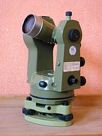
Structurally, theodolite consists of the following main nodes:
- Case with horizontal and vertical reading circles, and other technological units;
- A stand (sometimes the term “tribrach” is used) with three lifting screws and a round level (for leveling the theodolite);
- Spotting scope;
- Guide and fixing screws for pointing and fixing the telescope at the object of observation;
- Cylindrical level;
- Optical plummet ( plummet ) for exact centering over a point;
- Reference microscope for taking readings.
Theodolite horizontal circle
Theodolite’s horizontal circle is designed to measure horizontal angles and consists of a limb and an alidade .
The limb is a glass ring, on the beveled edge of which equal divisions are applied using an automatic dividing machine.
The price of division of the limb (the magnitude of the arc between two adjacent strokes) is determined by digitizing degree (less often hail) strokes. Digits are digitized clockwise from 0 to 360 degrees (0 to 400 gon ).
The role of alidade is performed by special optical systems - reading devices. Alidad rotates around its axis relative to the fixed limb along with the upper part of the device; the countdown in the horizontal circle changes. If you fix the clamp screw and unfasten the dial , then the alidade will rotate along with the dial and the count will not change.
The limb is closed by a metal casing, protecting it from damage, moisture and dust.
Geometric conditions of the theodolite, their verification
Geometric conditions
- The axis of the cylindrical level in the alidade of the horizontal circle should be perpendicular to the axis of rotation of the alidade.
- The axis of rotation of the alidade should be mounted vertically (vertically).
- The sighting axis of the pipe should be perpendicular to the axis of rotation of the pipe.
- The axis of rotation of the pipe should be perpendicular to the axis of rotation of the alidade.
- The vertical thread of the mesh should lie in the collimation plane.
Theodolite calibration
Verifications of the theodolite are called actions with the aim of identifying whether the geometric conditions presented to the instrument are fulfilled. To fulfill the violated conditions, a correction is called a tool adjustment .
The axis of the cylindrical level of the horizontal circle alidade should be perpendicular to the axis of rotation of the alidade
This condition is necessary to bring the axis of rotation of the tool (alidade) to the working position, that is, that it should be vertical when measuring angles. To verify the fulfillment of the condition by turning the alidade, the axis of the level to be checked is set in the direction of any two lifting screws and simultaneously rotating them in different directions leads to the level bubble at zero point (in the middle of the ampoule), then the level axis will take a horizontal position. Let's turn the alidade, and with it the level exactly 180 degrees.
If, after bringing the level bubble to zero, and turning the alidade through 180 °, the level bubble remains in place, then the condition is fulfilled.
To perform other checks, it is necessary to bring the device into working position.
One of the threads of the mesh should be in a vertical plane
Verification and adjustment of this condition can be performed using a plumb line installed 5-10 m from the tool. If the verified thread of the mesh does not coincide with the image of the plumb in the field of view of the pipe, then remove the cap, slightly loosen (about half a turn) the four screws that secure the ocular part with the pipe body, and rotate the ocular part with the mesh to the desired position. Fasten the screws and put on the cap.
After adjustment, the second thread of the mesh should be horizontal. You can verify this by pointing this thread to a point and rotating the alidade with the guide screw in azimuth ; the thread should remain at this point. Otherwise, the adjustment must be repeated. Having set the grid correctly, in the future, when repeating the verification, this can not be repeated.
The line of sight must be perpendicular to the axis of rotation of the telescope
This condition is necessary so that when the pipe rotates around its axis, the sight axis describes the plane, and not the conical surfaces. The target plane is also called collimation . The vertical circle rotates around the axis along with the pipe. To transfer the pipe from the KP position to the KL position or vice versa, it is necessary to transfer it through the zenith with a fixed dial and turn the alidade by 180 ° in the eye so that the pipe can be pointed at the same object at its different positions. At the same time, the diametrically opposite vernier 2 will now be located in the place relative to the limb where vernier 1 is located, and the readings of the number of degrees taken on vernier I before the turn of the alidade and on vernier II after the turn of the alidade by 180 ° should be the same. If the line of sight is perpendicular to the axis of rotation of the telescope, then when pointing it at CP and CL to a remote point located approximately at the level of the axis of rotation of the telescope, we will get the correct arc counts using I (for CP) and II (for CL ) verniers. If the sighting axis is not perpendicular to the axis of rotation of the pipe and occupies the wrong position in the case of CP and CR, then an error corresponding to the rotation of the sighting axis by an angle, called the collimation error, will enter the readings along the horizontal dial. The projection of this angle onto the horizontal plane of the limb varies depending on the angle of inclination of the line of sight. Therefore, when performing this verification, the line of sight should be as horizontal as possible.
Adjustment: by loosening slightly one vertical, for example, upper, fixing screw with a grid of threads, move the grid by acting with side correction screws with it until the point of intersection of the threads coincides with the image of the observed point.
After adjustment, it is necessary to repeat verification and make sure that the condition is met.
The axis of rotation of the telescope should be perpendicular to the axis of rotation of the instrument (alidade)
This condition is necessary so that after bringing the instrument into working position, the collimation (sighting) plane is vertical. To verify the fulfillment of this condition, the tool is brought into working position and the point of intersection of the grid of threads is directed to a high and close (at a distance of 10–20 m from the tool) point selected on some bright wall. Without turning the alidade, they tilt the pipe with the lens down to the approximately horizontal position of its axis and mark on the same wall the point at which the point of intersection of the threads is projected. After transferring the pipe through the zenith, at a different position of the circle, the target axis is again directed to the same point and, like the previous one, tilting the pipe to an approximately horizontal position, mark the point.
If both points coincide at one point, then the condition is satisfied.
The fulfillment of the condition under consideration is provided by the factory or is carried out in the workshop, as modern theodolites do not have the corresponding corrective screws.
The zero point of the theodolite’s vertical circle must be constant [2]
For verification, theodolite is horizontal and 2-3 times determine the place of zero. The determination of the zero point includes sighting at the same point in CR and CP. Each time you hover over a selected point, the vertical circle of the theodolite is counted. If there is no compensator, then previously the level bubble in the alidade of the vertical circle must be set to zero point. If the oscillations of the zero point do not exceed the double accuracy of the reading in a circle, then we can assume that the verification is performed, in exceptional cases, additional measurement is made through the balance of the axes.
Standard series of theodolites of Russia in accordance with GOST 10529-96 [3]
Types of theodolites:
OT-02, OTB, OTS, TB-1, Theo-010, TE-B1, T1, T2 - high-precision
T5, OTSh, Theo-020, TE-C1, TT-4, OMT-30, TT-5, TTP, TN, TG-5, T15 - accurate
T30, Theo-120, TE-E4, TT-50, TOM, Te-5 - technical
T60, TM-1 - technical (currently not available) (used for training manuals and reconnaissance of the area in the expedition).
The letter T - means "theodolite", and the following numbers - the value of the mean square error in seconds, when measured in one step in laboratory conditions. The designation of the theodolite made in recent years may look like this: 2T30MKP. In this case, the first digit shows the modification number (“generation”).
M - surveying performance (for work in mines or tunnels; can be attached to the ceiling and used without a tripod , in addition, in the surveying theodolite in the field of view of the sighting tube there is a scale for observing the swing of the plumb when transmitting coordinates from the surface to the shaft).
To - the presence of a compensator that replaces the levels.
P - direct viewing telescope, that is, the theodolite telescope has a wrapping system to obtain a direct (not inverted) image.
A - with an autocollimation eyepiece (autocollimation);
E - electronic.
Repeatable Theodolite
Repeating theodolites have a special repeating system of axes of the limb and alidade, allowing the limb together with the alidade to rotate around its own axis separately and / or together. Such a theodolite allows sequential rotation of the alidade to postpone (repeat) several times on the limb the value of the measured horizontal angle, which increases the accuracy of the measurements.
Non-repeatable theodolites
In non-repeatable theodolites, the limbs are tightly fixed with a stand, and rotation and fixing it in different positions is carried out using fixing screws or a turning device.
Phototheodolite
Phototheodolite or film theodolite is a type of theodolite combined with a photo and / or film camera and other optical systems. Serves for accurate photography with angular reference of geological objects and artificial structures, as well as for measuring the angular coordinates of aircraft . Structurally, it can be a movie camera independent of the optical channel of theodolite and rigidly attached to it or a single-lens reflex camera, the viewfinder of which serves as the optical channel of the theodolite. Previously produced film theodolites were shooting on high-resolution large format photographic plates. At present, film, plate, and digital phototheodolites are produced. If an object is photographed by two or more phototheodolites, it is possible to obtain approximate data on the size of the object, altitude and speed of flight.
Theodolite Models
- In Russia, the first film-phototheodolite station for photographing flying objects and measuring flight path parameters was released by the Krasnogorsk Plant named after S. A. Zvereva
- The Zvenigorod observatory is equipped with the KST-50 cinema theodolite (D 450 mm, F 3000 mm)
- High-precision cinema theodolites "VISMUTIN" manufactured by BelOMO are located at the Baikonur Cosmodrome .
Gyrotheodolites
Gyrotheodolite
Gyrotheodolite is a gyroscopic sighting device designed for orienting tunnels , mines , topographic reference, etc. A gyrotheodolite is used to determine the azimuth (bearing) of an oriented direction and is widely used in surveying, geodesic, topographic, and other works. According to the principle of action, gyrotheodolite is and belongs to the type of gyrocompasses . A number of schemes of gyrotheodolites are made on the principle of the Foucault gyrocompass . In addition to the gyroscopic sensing element, the gyrotheodolite includes a goniometer device for taking readings of the position of the sensing element and determining the azimuth (bearing) of the oriented direction. The goniometer consists of a limb with degree and minute divisions, tightly connected with its alidade. Observation is carried out along a line projected on a mirror, which is mounted on a sensitive element. In this case, the line of sight of the telescope will be parallel to the axis of the gyroscope . The azimuth ( bearing ), which is oriented using the gyrotheodolite of the direction, is determined on a scale associated with the theodolite. In observations of gyrotheodolite, all measurements are related to a plumb line at the observation point and to the horizon plane. Therefore, the azimuth, determined gyroscopically, is identical to the astronomical azimuth. Typically, for structural reasons, the reading device in a horizontal circle is placed at a certain angle with respect to the axis of rotation of the gyro rotor . [four]
Gyrostation
In essence, the same gyrotheodolite with a Foucault gyrocompass based on an electronic total station.
Electronic
Electronic theodolite - a type of theodolite equipped with an electronic reading device.
Total
A kind of electronic theodolite equipped with an electronic device for calculating and remembering the coordinates of points on the ground and a laser range finder . Unlike optical non-repetitive, it completely eliminates the errors of reading and recording the count due to the microprocessor that performs automatic calculations. Electronic theodolite allows you to work in the dark.
Total station
An electronic total station or optical theodolite equipped with additional devices (range finder, GPS-receiver, controller (processor and / or keyboard), separately removed from the main body of the instrument.
Notes
- ↑ Distance measurement with a rangefinder (Inaccessible link) . edu.dvgups.ru. Date of treatment May 26, 2016. Archived on May 1, 2016.
- ↑ Kuznetsov P.N. Geodesy. Part 1: Textbook for universities. - M .: Kartgeotsentr - Geodeizdat, 2002 .-- 341 p.: Ill. ISBN 5-86066-049-9
- ↑ GOST 10529-96 “Theodolites. General specifications "
- ↑ gyrotheodolite in TSB
See also
- Theodolite horizontal circle
- Total station
- Level
- Radio theodolite
- Sextant
- Compass
Links
- Theodolite device
- Theodolite on a site about geodesy and geoinstruments