S-II - American missile stage . It was used on the Saturn V booster rocket as a second stage; it worked on the launch site in the upper atmosphere. Manufacturer - North American Aviation . Fuel - liquid hydrogen, an oxidizing agent - liquid oxygen. Thrust - 5 MN.
| S-ii | |
|---|---|
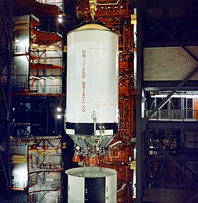 Step S-II in preparation for the launch of the Apollo 6 ship, in a vertical assembly building | |
| General information | |
| Manufacturer | |
| A country | |
| Rockets | Saturn V (stage 2) |
| Dimensional and mass characteristics | |
| Length | 25 m |
| Diameter | 10.1 m |
| Weight | starting: 458.7 t dry: 37.6 t |
| Remote Control Features | |
| Marching " J-2 " | |
| Type of remote control | Rocket engine |
| amount | five |
| Thrust | 5115 kN (total) |
| Specific impulse | 421 c |
| Working hours | 367 s |
| Fuel | liquid hydrogen |
| Oxidizing agent | liquid oxygen |
Creation History

The development of S-II began in December 1959 when the committee made recommendations for the design and manufacture of a high-thrust liquid hydrogen engine. The contract for this engine, which later received the designation J-2, was received by the company Rockettine . At the same time, the design of the S-II stage began to take shape. Initially, it was supposed to be 22.5 m long and 6.5 m in diameter, with four J-2 engines.
In 1961, the Space Flight Center. Marshall began to search for a contractor for the construction of the stage. Of the 30 aerospace companies invited to the meeting, where the initial requirements were announced, only seven proposals were accepted for consideration in a month. After studying, three of them were rejected. However, it was later decided that the initial specifications of the entire rocket were too underestimated and therefore it was necessary to increase the size of all stages. This caused difficulties for the four remaining companies, because NASA has not yet decided on various aspects of the stage, including the size and type of upper stages that should have been installed on it.
Ultimately, on September 11, 1961, a contract was signed with North American Aviation (which also received a contract for the Apollo command and service module ), which was built by the government in Sea Beach , California .
Design
Stage S-II consisted of an upper adapter, fuel tanks, an engine compartment with five J-2 rocket engines, a lower adapter between the first stage of S-IC and the second stage of S-II. The fuel compartment included a 370 m³ spherical liquid oxygen tank (360 tons of liquid oxygen) and a 1,100 m³ cylindrical liquid hydrogen tank (70 tons of liquid hydrogen). At full refueling, S-II weighed about 481 tons, 7.6% was the weight of the stage itself, 92.4% was the weight of the fuel and oxidizer.
Five J-2 engines were installed in the lower part of the stage: one was fixedly fixed in the center, the remaining four were mounted on the outer ring in cardan suspensions, they could be rotated to control the thrust vector.
The hydrogen tank was coated with heat insulation to reduce losses from the evaporation of liquid hydrogen. Thanks to this, the weight of the step was reduced by 1.4 tons. Oxygen and hydrogen tanks had a common bottom, consisting of a sandwich structure - two aluminum shells with a honeycomb filler based on phenol between them. As a result, a degree of thermal insulation was achieved, which ensured a temperature difference between the two tanks of 70 ° C. The use of a common bottom allowed to save 3.6 tons of weight compared with the option with individual bottoms.
The liquid oxygen compartment is an ellipsoid container with a diameter of 10 m and a height of 6.7 m. It is welded from 12 wedges and two round parts at the ends. Each of the wedges was obtained through a thoroughly organized series of three underwater explosions inside a 211,000-liter tank. The liquid hydrogen compartment consists of six cylinders: five 2.4 m high and sixth 0.69 m high. Thermal insulation was the most difficult, since liquid hydrogen should be stored at a temperature not exceeding 20 K (−252 ° C). Initial decisions were unsuccessful: leaking weld fragments and gas bubbles were encountered. The final option involved the manual application of a heat-insulating coating with a spray, followed by removal of excess. The S-II was designed vertically to simplify welding and to ensure the correct shape of large circular parts.
The pressurization of the fuel and oxidizer tanks is carried out by gasified hydrogen and oxygen, respectively.
On the lower adapter, 8 solid-fuel solid-fuel rocket engines were installed (each brake solid propellant rocket engine had a thrust of 39 tons, an operating time of 0.66 s), which were started after the first stage was separated in order to precipitate fuel in the S-II tanks before starting its engines. (The principle of cold separation of steps was applied to Saturn launch vehicles) 30 seconds after the engines were started, the adapter was reset by pushers. [one]
On the upper adapter there are 4 solid-fuel braking rocket engines that start after the separation of the third stage, S-IVB , and brake 2 stages. [one]
As in the first stage of the S-II, 5 engines, one in the center and four on the periphery, by turning the latter, rocket control is achieved. J-2 engines, each of which gives traction of 102 hardware.
The second-stage propulsion system operates for approximately 390 seconds and turns off at an altitude of 186 km at a flight speed of 6.88 km / s.
Built Steps
| Serial number | Using | Launch date | Current location | Notes |
|---|---|---|---|---|
| S-ii-f | It was used as a replacement at the stage of dynamic strength tests after the destruction of samples S-II-S / D and S-II-T. | US Space & Rocket Center , Huntsville , Alabama . | ||
| S-ii-t | Destroyed by the explosion of May 28 , 1966 . | |||
| S-II-D | Development canceled. | |||
| S-II-S / D | Sample for static and dynamic strength tests. | Destroyed at a test bench on September 29 , 1965 . | ||
| S-II-1 | Apollo 4 | November 9 , 1967 | She carried markers for pointing cameras located around the circumference of the front “skirt” and cameras for video recording of the first stage compartment. | |
| S-II-2 | Apollo 6 | April 4 , 1968 | I carried cameras for filming the first-stage compartment. | |
| S-II-3 | Apollo 8 | December 21 , 1968 | ||
| S-II-4 | Apollo 9 | March 3 , 1969 | 1800 kg lighter, 600 kg more allowable load, more powerful engines and a larger supply of liquid oxygen. | |
| S-II-5 | Apollo 10 | May 18 , 1969 | ||
| S-II-6 | Apollo 11 | July 16 , 1969 | ||
| S-II-7 | Apollo 12 | November 14 , 1969 | ||
| S-II-8 | Apollo 13 | April 11 , 1970 | Failure of the central engine of the second stage during the lift due to POGO-oscillations . | |
| S-II-9 | Apollo 14 | January 31 , 1971 | ||
| S-II-10 | Apollo 15 | July 26 , 1971 | ||
| S-II-11 | Apollo 16 | April 16 , 1972 | ||
| S-II-12 | Apollo 17 | December 7 , 1972 | ||
| S-II-13 | Skylab-1 | May 14 , 1973 | Improved for use as the last stage. | |
| S-II-14 | Apollo 18 (canceled) | N / a | Kennedy Space Center | Intended for the canceled version of Apollo 18. |
| S-II-15 | Intended for the station, which was a backup for SkyLab 1 (did not fly) | N / a | Johnson Space Center | Intended for the reserve station "Skylab" SA-515 which NASA did not use. |
Notes
Literature
- Rocket Engineering Series, Volume 3, I. I. Shuneiko, Manned Flights to the Moon, Design and Features of Saturn V Apollo, Moscow, 1973.
- V. I. Feodosiev, “Fundamentals of rocket flight technology”, second edition, revised, M., “Science”, GRFML, 1981, pp. 75-89
- Bilstein, Roger E. (1996). PDF format Stages to Saturn: A Technological History of the Apollo / Saturn Launch Vehicles. NASA SP-4206. ISBN 0-16-048909-1 .
- Apollo Systems Descriptions, Volume 2.